Some time ago, many friends asked about the electronic fence. The electronic fence is also a common project in the construction of weak electricity. In this issue, we came to the knowledge about the installation and construction process of the electronic fence system.
Investigate the setting of the installation place of the electronic fence: the electronic fence is required to have no conflicts with the wires and pipes in the underground and air direction; there is no debris in the vicinity of the fence; whether there is a strong interference source near the installation location of the fence device (such as the launch pad, etc.) High-frequency equipment), if any, indicate that the signal line must be shielded twisted pair in the construction drawing.
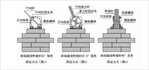
First, determine the installation angle of the perimeter fence (the angle with the top surface of the wall)
According to the situation of the site and the requirements of Party A, determine the perimeter fence angle (0°, 22.5°, 45°, 67.5°, 90°, 112.5°, 135°, 157.5°, 180°) and the tilt direction (inward tilt, camber) Type, vertical or horizontal installation).
According to the perimeter environment: residential areas and schools are recommended for inward or vertical installation. The open area is recommended to be cambered. Horizontal installations can be used when the wall is above 2.5 meters. According to the protection object: it is recommended to install the external installation when preventing external invasion. It is recommended to be introverted when preventing internal overturning.
Second, the assembly of the bearing rod and the bearing rod insulator
1. Fix the bearing rod insulator with the self-tapping screws on the bearing rod, paying attention to the same direction.
2. As shown in the figure: Fix the bearing column on the universal base with screws. The universal base is divided into 16 holes to adjust the installation angle according to the hole position. (Note: the line of the fence alloy wire and the two fixing holes of the universal joint are perpendicular to each other, and the installation inclination meets the requirements of 1).
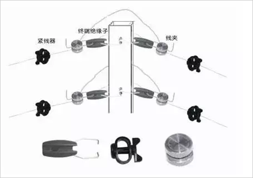
Third, assembly terminal rod and terminal rod insulator
1. Fix the terminal rod insulator to the terminal rod with the terminal insulator fixing clip. Pay attention to the same direction. Use the terminal rod insulator and the terminal rod in a clever way when turning or falling.
2. Secure the terminal rod between the two universal bases with bolts.
3. Where there is a fence controller, one or two (vertical to each other) arrester fixtures should be added to the top of the terminal rod.
Fourth, the use of the intermediate tightener instructions
The intermediate retractor is always hung on the front fence. When the alloy wire is installed, the alloy wire is inserted through the circular hole on the side of the intermediate tensioner, and then aligned and passed through the middle slit in the middle, and finally through the other side. The hole is pierced.
Fifth, the installation of the fence terminal rod
1. Determine the specific position of the fence struts: punch the holes with impact drills at the top of the fence, and fix the struts in the appropriate position with M10×100 (M8×80 with intermediate rods).
2. Place an intermediate load-bearing rod every 5 meters or add an intermediate load-bearing rod at other necessary positions.
3. At each corner and at both ends of the zone, when the height is not more than 100 meters or other tension is relatively large, it is necessary to install the terminal rod. The partition should be installed with insulators from two directions.
Terminal rod assembly and installation diagram
Sixth, the installation of the arrester
The arrester should be fixed on the arrester mounting bracket by its own nut. The arrester is usually installed above the pulse host, and a pair of arresters are installed in each zone.
Seven, the installation of the fence line
1. Principle:
1) One zone is a series circuit, which must be connected in series from the host to the electronic fence. At the junction of the wires, high-voltage-resistant wires must be connected to avoid gaps or short-circuits.
2) The principle of grounding, the grounding point is generally selected at the end of the electronic fence, but when the zone is added to the arrester, the grounding point of the arrester should be at the beginning of the electronic fence.
3) Strong current and lightning arrester must have good grounding and grounding resistance <10Ω.
4) The strong and weak grounding must be separated and ≥4m.
2, installation points:
1) The fence line should be fixed by means of segmented installation. The same line or the same zone is recommended to be divided into one section. Cables that are not on the same line are installed several times.
2) Spreading the alloy wire: use the pay-off frame or the appropriate way to release the wire, and do not let it be placed arbitrarily to avoid knotting and unevenness. You can spread the four at the same time, but be careful not to cross.
3) Tightening wire: Fix one end of the alloy wire with a wire connector (or self-winding) on ​​one end of the terminal rod insulator, and then place the four alloy wires into the slot of the intermediate rod insulator or the bearing rod insulator. Finally, thread the wire tensioner and firmly tighten the alloy wire and fasten it to the terminal rod insulator at the other end with a wire connector (or self-winding). Then adjust the tensioner so that the 4 lines are tight at the same time and parallel to each other. Parallel lines should be tensioned at the same time.
Eight, grounding body production
A grounding body must be inserted under each host, and a grounding body should be set every 100m. The grounding body standard: more than 40×40×4×1500mm (with grounding bolts or holes of M10 or more), standard galvanized grounding angle iron, vertical Into the ground, the grounding body is reliably connected to the arrester bracket and the booster grounding terminal, and the grounding resistance is <10Ω. When it is not enough, a drag reducing agent can be added. The strong electrical ground and the weak electrical ground must be isolated from each other and must have a distance of > 4 m.
Nine, RS485 signal control line, fence controller power line laying
If there is a pre-buried pipeline, it can be directly used. Otherwise, the PVC pipe is used for pipe laying. The laying requirements are in line with the pipe wiring requirements. The main pipes are: RS485 signal control line RVSP2×0.75mm? Round twisted pair, fence controller The sheathing wire of the power cable RVV2×1.5 mm (from the mainframe and connected to each fence controller, the wire diameter needs to be increased by more than 600m).
Ten, the installation of warning signs
Install the “Electronic Fence Prohibited Climbing†warning sign, which can be fixed on the fence line with alloy wire.
Eleven, fence controller (host)
1. Install the fence controller under the fence and the fence partition, so that the fence controller and the fence are separated by about 40cm, and fixed to the wall with expansion bolts.
2. Make a good connection between the fence controller and the grounding flat iron. The fence controller is grounded (weak grounding, connected to the shield of the communication line) and isolated from the grounding of the high-voltage fence (strong grounding) to avoid interference.
3. Connect the high-voltage lead of the fence controller to the fence through the PVC wiring tube. The joint should be connected by wire connector (or self-winding).
4. The RS485 bus, alarm output line, and power line are separated from the high voltage line, and a separate wiring tube is used.
5. Connect the high-voltage arrester reliably between the start of the perimeter fence and the ground (note the waterproof direction).
12. RS485 communication between the host and the keyboard
RVSP2*1.0 cable connection between the host and the keyboard is acceptable.
Description: Back-up rolls for cold strip mill, Forged Steel Back-Up Rolls is mainly used in 4 Hi and 6 Hi mills, the diameter of roll barrel can be 350mm-1500mm.
Material: Forged Steel, Chromium 3% , Chromium 4%, Chromium 5% or as per the customer`s requirement.
Barrel Diameter: 1500mm maximum
Unit weight: 25mt/pc
Type: Single rolls, forging.
Cold Mill Back-Up Rolls,Forged Steel Back-Up Rolls,Cold Mill Roll,Cold Mill Work Roll
Shijiazhuang BKDR Metallurgical Science & Technology Co.,Ltd , https://www.bkdrtech.com