In order to scientifically carry out innovative design of machine tool products, a new creative machine tool design method has emerged in recent years. This method analyzes the forming motion of the machined surface according to the information of the tool and the machined surface, and creates the movement function. Motion function module. The preparatory motion function modules are combined according to different assembly relationships to form a general layout plan of the machine tool. This paper mainly introduces how to create the motion function module and assemble the module. 2 The basic structural form of the machine tool is based on sports.
The motion structure created by the motion function is not image. To associate the movement of each coordinate direction with one or more moving parts, we call this moving part the basic motion function module, with the basic motion function module. The structural form of the machine tool can be created to make the structure of the motion structure visualized.
2.1 The basic size of the functional module is created in the motion function structure of the machine tool. 13 is based on the ground. The side is assigned with 2 coordinates and 7 coordinate directions. The main motion is the rotary motion of the knife. The wide separator will be divided into the tool side and the workpiece side to introduce the method and steps of the machine structure.
Establish the overall coordinate system of the machine tool to determine the machining space.
The movement stroke is initially determined by the machining space.
The tool spindle orientation is determined from the coordinate system. For example, the tool's boring and telecontrol is a selective layout of the spindle box.
3 Determine the structural form of the tool side motion function. The relevant shape and size of the joint portion and the lower module are determined according to the enamel of the telekinetic travel motor element and the upper module. 1 Determine the structural form of the workpiece side motion function. For example, based on the processing space of the workpiece. It can be determined that the position of the table can determine the length or width of the base according to the direction of the stroke and the size of the joint of the table. The height of the base is determined to meet the requirements of the dimension of the dimension in the machining space. In consideration of the stroke retraction and interference, etc., it is necessary to coordinate the size of the person.
2.2 Data structure of the motion function module Description The spatial size and shape of the motion function module can be passed by. Person 03 uses the following data structure and method to describe the top and bottom diameter and height of the cylinder or the round table ReJZSideN; the length of each side of the polygon; set the module size with the motion function structure as the basis for each motion function module in the space should meet the assembly relationship . That is, the starting position of any motion function module in space depends on the position and size of the 1 function module. And its position and size affect the starting position of the next function module, so the above data structure and method only describe the function module can not realize the automatic assembly of space between the modules, and can not achieve the ruler in Parameterized drive. Therefore, it is necessary to add a description parameter and method to the data structure of the function block. Specifically, the intModelJNo detects the direction vector s of the module, intModelJNo; sets the starting vector s of the module's direction vector setting module, intModelNo; the starting vector of the detecting module refers to the function of the shuttle block data structure and method to describe the function module.
It can be frequently separated and assembled and adjusted during the design process.
In addition, let the function module database, the size parameter driving function module of the library 3 module assembly of 4.0 have the above method of describing the parameters, and provide the necessary basis for the assembly between the modules, and to truly complete the space between the modules. The assembly must also establish the geometric constraint relationship between the modules. 3.1 Geometric constraint relationship The geometric constraint relationship is the geometric constraint of the parameter-based parameterization technique.
Geometric constraints can be divided into two major types of structural constraints and dimensional constraints.
The structural constraints are based on the topological relationship between geometric elements or other concatenations including parallel vertical oblique tangent and concentric fitting symmetry. 2. Non-relational constraints include self level and self vertical.
The size constraint is determined by the size of each geometric element, such as the distance angle radius diameter chamfer.
3.2 Assembly relationship After the shape and size of each component shuttle block are determined. The assembly relationship between them is defined by the relationship constraints. The size and shape of the component modules are constantly being modified during the design process. In order to make the modified tax block not affect the overall assembly relationship of the whole machine, before getting the overall assembly, all modules must be traversed to judge the connection relationship and topological relationship between the modules, and record them. To this end, a 3 chain member 1 block 1I is occupied by the bi component module I component, and a block I relationship pointer is defined. The data structure adopted in this paper is beneficial to realize the size parameter driving, that is, when the size of the component module is changed, the topological relationship between it and other component modules is unchanged. It is more conducive to serialization of standardized design and payment of existing designs for inheritance modification. 27; 7 horizontal plus 1 center, gt; layout design, to assess the feasibility of the software system.
The shape of the parameter input component group The maximum size of the body part group Length, width, height = 800tniiXl200tnniX600tnni After dimensioning the horizontal machining core, the following main techniques are based on the dynamic characteristics of the grinder bed structure optimization layout design Chen Xin He Jie Mao Haijun Chen Nan, Sun Qinghong, Southeast University, 1 Abstract The finite element method was used to analyze the structure of the internal grinder bed, and the buccal and dynamic analysis was carried out. The influence of different layouts of the internal ribs on the dynamic structure of the bed structure was discussed. Layout is the key to improving the dynamics of the bed. 1 Introduction The dynamic characteristics of the bed structure are closely related to the overall performance of the machine tool, and the dynamic characteristics of the machine bed. It is of great significance to ensure the accuracy of the machine tool. The traditional machine bed design is still in the design stage of empirical static analogy. It is difficult to consider the influence of the dynamic characteristics of machine parts on the performance of the whole machine. In this paper, the human milk 5 software is used to establish the limit model of the inner grinder bed and the improved scheme. Find out the defects of the dynamic characteristics of the bed, analyze the dynamic characteristics of the model, and explore the way to realize the dynamic optimization design of the machine.
2 Analysis model 21 structure dynamics model and analysis structure parameters spindle outer diameter 0l28.57mnu tool maximum diameter 0125nmi according to the motion function structure and layout rules to determine the basic size and assembly relationship of the horizontal machining center functional modules, using the software to generate 4 The overall layout.
1 Zhang Guangpeng. Huang Yumei and so on. A creative approach to the design of machine tool motion functions. Combined machine tools and automated processing technology 199922 Feng Xinan, Huang Yumei. Mechanical manufacturing equipment design. Beijing Mechanical Industry Press, 1999, 10 Dijon Peak, Xi'an University of Technology School of Instrumentation, zip code editor Zhao Honglin received revised date 200, 521 parameters of the 7 special. 277 horizontal processing center overall layout Jiangsu Province nine major industrial research projects 980062.
There is a large window on the front wall of the bed, the internal ribs are horizontal and horizontal, and there are a number of reinforcing small ribs, the bottom is closed, and the outer wall of the bed is 18 slab thick.
3 The finite element chess type 13 first-order vibration type bed adopts a single body. Modeling 13. The order vibration frequency is 289.5, which is a torsional vibration with a large relative displacement.
(Finish)
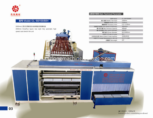
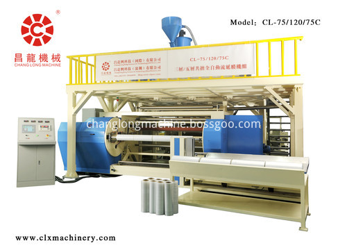
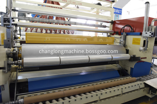
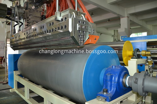
2000mm three/five layers fully automatic co-extrusion stretch film unit is based on our 30 years` professional skills and continuous improvement, the whole line comes true fully automatic production, based on traditional automatic cut film, increase automatic change paper core and automatic unloading finish film system, comes out four volumes of 500mm width for one time , ensure stable extrude with high output, high linear speed and save labour cost.
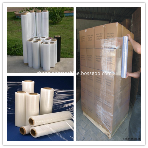
The film produced by the this winding stretch film machinery is suitable for the rapid transport or storage, its strong adaptability, high efficiency and low energy consumption can make goods integrity to prevent goods from loosening and collapsing during transportation and being polluted by dust.
*Related Products:wrapping film extruder machine,plastic film extruding machine.
Machinery pictures:
Produced Films

2000mm stretch film machine unit
2000MM Black Stretch Film Machine Unit,2000MM Hand Stretch Film Machine Unit,2000MM Plastic Stretch Film Machine Unit,2000MM Packaging Stretch Film Machine Unit
CHANGLONGXING SCIENCE & TECHNOLOGY (SHENZHEN) CO.,LTD , https://www.clxmachinery.com