As the application research of soil moisture sensor, the paper completed the hardware and software design of the portable soil moisture measuring instrument, developed the prototype of the system, verified the performance through experiments, achieved the design requirements, realized the GPS data receiving and processing, soil The function of water collection and storage, and the use of GIS software ArcView to generate soil moisture distribution map to monitor the soil moisture content, provide the basis for the implementation of variable irrigation.
Due to the spatial differences in soil structure and soil moisture, the soil moisture content in the same plot is different, which requires the monitoring of flood conditions and variable irrigation techniques. Variable irrigation is one of the major development directions of current precision agriculture and forestry and is a powerful measure to achieve water-saving agroforestry. Based on the requirements of variable irrigation, this paper designs a portable soil moisture meter. The application of the portable soil moisture meter can be divided into two parts: (1) When sampling in the field, the RS232 serial port of the SCM system is connected with the serial port of the GPS receiver to realize communication with the GPS receiver. At the same time, an analog signal input port of the SCM system is connected with the SWR soil moisture sensor probe to measure the soil moisture content, and then combined with the time and geographical data sent by the GPS receiver to form a data block and stored in the RAM of the SCM system. For transmission to the host computer for data processing. (2) In the data processing in the studio, the RS232 serial port of the single-chip microcomputer system is connected with the RS232 serial port of the host computer, and the data block stored in the RAM is transmitted to the host computer for a series of data processing. Generate soil moisture maps to monitor field soil moisture and guide variable irrigation. The main functions of the system are shown in Figure 1.
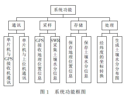
Figure 1 System Functional Block Diagram of Portable Soil Moisture Tester
The system hardware structure design of the portable soil moisture measuring instrument is based on the functional requirements of the system. Corresponding hardware must include: RS232 port for communication with GPS and host computer; function port for receiving SWR soil moisture sensor information; information display part; program and data storage ; function keyboard.
The system software design system of the portable soil moisture measuring instrument can be divided into two parts: one part is the single-chip microcomputer system, which is responsible for control and data receiving and storage; the other part is the upper computer system and is responsible for data processing. Taking into account the characteristics of the two parts and the difference in the implementation of functions, use different language tools to achieve.
The single-chip microcomputer system of the portable soil moisture measuring instrument adopts C language as the programming language. C language has many advantages such as powerful function, good portability, easier programming and structured design, and higher program readability, and its compiled code is compact, and its structure is excellent. Its operating efficiency is close to that of assembly language. At present, the more popular programming tools in the Windows platform of the PC are VC, VB, DELPHI, etc., taking into account the functional requirements of the host computer and the limitation of development time. The system adopts strong functions, high efficiency, and rapid development. The development tool VB as a host computer development platform.
Portable Soil Moisture Tester MCU system software design: MCU part of the program can be divided into four parts: the main control module (main program), event acquisition and execution module, sub-function module (mainly key function module and communication module), Display module. The main program of the main program is the entry and initialization part of the whole MCU program, and it is the main part of the program operation and the general control part. After the main program is started, the event module cyclically obtains the state of each key event and executes the key event. The event execution module then calls the corresponding sub-function module to complete the functions required by the user, and the display module displays the system running state and data results. The system needs real-time monitoring of geographic location information (ie, GPS information). Therefore, when the system starts to run, it must communicate with the GPS receiver, and the display module should display the geographic location information. This requires that the system's communication with the GPS receiver and the display of GPS information be done during the initialization phase of the main program. MCU system and GPS communication software design GPS receiver and microcontroller system communication is completed in a timer interrupt mode, a format of GPS data reception, and the serial port to work in a search mode, to ensure the completion of a timing interrupt to receive a format GPS all data. This makes the program structure simple, reliable and easy to implement. This communication program is divided into three major modules: (1) Set up GPS: Including setting GPS working status, base station, beacon, communication baud rate 9600bps, output format, etc. This part adopts the system provided by GPS developer. (2) Set the communication status of the SCM system: including setting the baud rate of the SCM to 9600 bps, the timer timing time 1s, and the timing interruption word. (3) Interrupt service module: includes reading, verifying, and storing GPS data.
The communication software design of the portable soil moisture meter and the host computer's communication software: The communication between the single-chip microcomputer system and the host computer adopts the point-to-point communication method. Among them, the one-chip computer system is the sender, the upper computer is the receiver. When the SCM system starts to send, it sends an “S†signal first, and the upper computer answers “A†after receiving it, indicating that it agrees to receive. When the MCU receives “Aâ€, it starts to send data. Every time it sends a “Checksumâ€, the data block length is 36 bytes and the data buffer is buf. After the data block is sent, “Checksum†is sent immediately. .
Brake Pads For Great Wall,Great Wall Brake Pads,Great Wall Car Brake Disc,Great Wall Service Brake
Ningxia Rossking Auto , http://www.rosskingauto.com