1 Structure and working principle
As shown in Figure 1, the vortex flowmeter consists of a vortex generator (triangle column), a test head, a watch body, a connection pillar, and a detection amplifier.
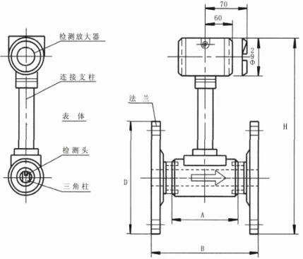
Figure 1 Vortex flowmeter composition
The LUGB type vortex flowmeter sensor is a kind of flow sensor that is designed and manufactured using Karman vortex street principle and modern electronic technology. Applicable to the measurement of liquid, gas and steam flow in various industries, and can measure turbid liquid containing impurities and tiny particles.
When the fluid to be measured flows through the vortex generator, two columns of vortices are alternately generated on the two sides of the back of the generator to form a “vortex street†as shown in FIG. 2 . The frequency of this vortex is proportional to the velocity of the fluid, and it satisfies the following formula under certain conditions:

Where: f: frequency of vortices St: Strouhal number V: flow rate d: width of vortex generator
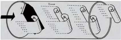
Fig. 2 Sketch of vortex street
The vortex generates alternating fluctuating pressure at the rear of the vortex generator body, which is converted into an electrical signal by a piezo-electric signal sensor and processed by the transmitter to be transformed into a pulse or standard signal output.
2 Technical Features
(1) Wide range of flow measurement, high measurement accuracy, and low pressure loss. The nominal diameter is DN10~DN500.
(2) Simple structure, no rotating parts, reliable work, good durability and long life.
(3) Measurement accuracy is not affected by fluid pressure, viscosity, and density. Widely used and industrial measurement, accuracy class 0.5.
(4) Strong resistance to environmental shocks. Measurable temperature up to +380 °C.
(5) Signal output current +-4~20mA, pulse signal, HART protocol, etc., use a wide range.
(6) Suitable for gases, liquids, steam and other media.
3 Application of flowmeters
Sensor selection mainly considers the choice of instrument diameter and instrument function and instrument pressure loss.
3.1 Selection of instrument caliber
The scope of the meter is different, and its measurement range is different. The measurement range of each type of caliber changes with the type of medium to be measured and the temperature and pressure of the working conditions. Select instrument diameter, according to the measured media type and operating conditions under the temperature and pressure of the flow, through the look-up table method to select the instrument diameter, for the superheated steam flow range through the look-up table, to detect the density of the measured medium, and then from the table The flow range was found at similar density.
For density values ​​in the table between two values ​​can be calculated proportionally.
Several flow conversion formulas:
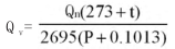
(1) The volume flow rate Qn in the standard state is replaced by the volume flow rate Qv in the working condition:
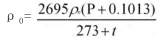
(2) Calculation of gas density under operating conditions: (density Ïn under standard conditions is converted to density Ï0 under working conditions)
(3) The mass flow QG is converted into the volume flow QV:

In the formula: Ïn - Density in the standard state, (kg/m3);
Qn-Volume flow in the standard state, (m3/h);
Qv-volume flow under working conditions, (m3/h);
Temperature at t-state, (°C);
P-state pressure, (MPa);
Ï0-Density at operating conditions (kg/m3).
3.2 Selection of Instrument Functions
The selection of the instrument output function is based on the application requirements. The general measurement flow selection sensor output is a pulse, and the power supply is +24V. When a field display is required, an on-site display sensor may be selected, and a 4-20 mA output may be selected according to the system function requirement. HART protocol output.
3.3 Calculation of Instrument Pressure Loss
After the meter diameter is selected, the pressure loss of the meter can be calculated and this will affect the process pipeline.
Formula: ΔP≤1.2ÏV
Where: ΔP - pressure loss of the sensor, Pa;
Ρ—density of the fluid, kg/m3;
V—average flow rate of fluid in the pipe, m/s.
3.4 Selection Examples
Select the original process pipe diameter DN100, medium is air, gauge pressure 0.35MPa, temperature up to 143 °C, estimate the standard state flow range 288~3000m3/h, requires the instrument to have the scene to show, and has 4~20mA output to the instrument room twice Instrumentation, on-site explosion protection, instrumentation accuracy level 1.
Solution: Replace the flow range of the standard state with the flow rate at the flow rate of 0.45 MPa under the working condition, using the formula
Use the formula to calculate the density Ï of the air under working conditions, lookup table under the standard state Ïn=1.293kg/m3
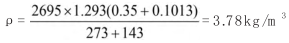
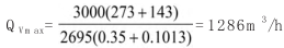
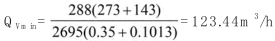
Look-up table in Ï=3.6kg/m3, DN100, working flow range is 100~2000(m3/h) If you calculate the lower limit flow rate by Ï=3.78kg/m3, it can satisfy Qvmin=123.44m3/h, so choose DN100 Sensor, full-scale Q operating condition max=1286m3/h (or standard Qmax=3000m3/h).
4 Instrument parameter setting and debugging
4.1 Calculation Formula:
(1) Instantaneous flow rate F = Fr (frequency) × 3600/K (flow coefficient)
(2) Cumulative flow = Instantaneous amount vs. time integral
Note: The instantaneous flow unit is: cubic meters/hour; flow coefficient: pulse number/cubic meter.
4.2 The display on the conversion board sets the parameters as follows:
There are three buttons from left to right on the display panel:
Location: Left key Middle key Right key
Running: Cumulative Instant Content
Settings: Shift TURN WORD Confirm and page
(1) Operating conditions
Press the accumulation key (left key) to display the 9-bit accumulation amount.
Press the momentary button (middle button) to display the instantaneous flow rate.
Press the content key (right key) to display instantaneous flow rate (F), frequency (Fr), output current (PE), flow coefficient (U), damping coefficient (Lr), flow rate upper limit (FH), flow rate lower limit (FL) Wait.
(2) In the setting state
Press the left button to shift the required setting word (flashing word);
Press the middle button to change the desired setting word (flashing word);
Right-click to confirm the page and turn pages;
(3) Setting method
Press the right button first, then press the middle button at the same time to enter the setting state. At this time, the display shows the flashing word of the flow coefficient (U), which can be shifted by the left button, the change of the flashing word in the middle button, and the right button. Confirm and turn pages to complete flow coefficient (U), damping coefficient (Lr), flow rate (FH), and flow rate (FL) settings. For example, set the flow coefficient to 123.45 and enter the setting state first. At this time, the display shows U-xxx and the first digit is flashing. Press the middle button to make the first digit display 1 and then press the left button. (move to the second place, at this time the second flashing), press the middle button to make the second place display 2, and so on, until the last one is set, confirm the setting number is correct, press the right button to confirm, At the same time, enter the next parameter setting. When all the parameters are set, press the right button and press the middle button to exit the setting state and enter the display state.
Free Forging,Forged Flanges,The Forging Flange,Oilfield High Pressure Pump
Zhangqiu Xinhao Machinery Parts Factory , https://www.xhflange.com