Abstract: Programmable controllers (PLCs) are used to replace relay control systems. They combine the advantages of complete computer functions, flexibility, and versatility with the advantages of easy-to-understand relay control, easy operation, and low price. A new type of industrial control device developed on the basis of hard-wired logic control technology and computer technology.
PLC has been widely used in the field of industrial control, and is more commonly used in the power industry. For example, chemical water program control, condensate polishing system and ash removal system, Tongling Power Plant 300 MW unit, ETS system is the first in Anhui Province to use PLC Units that implement their logical functions.
1. System Introduction The emergency shutdown system (ETS) consists of a simulation test board, an operation indicator board, a head test module and a control cabinet. The function of ETS is to accept the signal of the field device, and send an alarm signal when the parameters of the steam turbine exceed the limit. And through the AST solenoid valve discharge EH high pressure oil, close all steam inlet valve, emergency stop.
When a certain parameter of the steam turbine reaches the trip value, the detection signal acting on the tripping cabinet is closed. After logic processing of the tripping cabinet, four AST solenoid valves are driven, and the high pressure oil of the automatic tripping tripping pipe is drained, so that the high and medium pressure main Valves and adjusting doors close quickly. If the turbine speeds up to 103%, the OPC protection signal is sent by the DEH, so that the high pressure oil system blocks the two OPC solenoid valves in the module, and the 0PC high pressure oil is drained to close the high and medium pressure control door. Since two reverse check gates are provided between the automatic shutdown tripping busbar and the OPC busbar, the high and medium pressure main valves are still in operation. When the overspeed reaches 110%, the emergency shutdown system (ETS) acts, quickly closing the high and medium pressure main valves and regulating the doors to achieve emergency shutdown.
The system provides dual channel protection, allowing online testing to continue to provide continuous protection during testing.
There are 15 ETS design shutdown projects in this project: EH low oil pressure, low lubricant pressure, low vacuum, large axial displacement, 110% overspeed, high vibration (#1-8 watts), generator failure, high exhaust temperature , Low turbine pressure ratio, large differential expansion, boiler MFT, high pressure, high pressure, manual shutdown and ATC turbine shutoff, DEH power loss, etc., as shown in Table 1.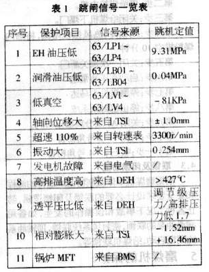
Each set of signals can give a "first out" memory signal, ie the first incoming signal can be memorized separately. Each set of signals gives two outputs, one signal to the SOE and the other to the BTG disk.
2. Implementation of Logic Function The system consists of two OMRON SYSMACC200HE (CPU42) programmable controllers A and B and corresponding I/O modules, which form two independent channels A and B, respectively, to realize the online channel. Test function. The A and B channels each include 3 digital input modules and 5 output modules. All digital inputs are passive contacts. In addition, two sets of passive contacts are sent for each set of trip signals, one set is provided to the DAS system for SOE, and the other is set to the BTG disk optical plate alarm display.
The first cause of tripping is flashed on the operation indicator and the subsequent tripping signal is indicated by a flat light. The system has ETS power failure and PLC fault alarm and first-out trip signal memory function.
The system's operating power supply capacity is 220V2KVA, which is powered by redundant UPS power supply and security power supply. The AST solenoid valve (normally-energized, normally-open solenoid valve) has a power supply of 110VAC, which is to turn 220VAC into 110VAC through a transformer in the control cabinet.
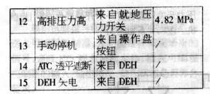
Figure 1 is a ladder diagram of a lubricant trip trip. 00000, 00001, 00100, and 00101 are input contacts of the PIC; 03000, 03003, 03006, 03010, and 00600 are coils of the PLC and are used instead of hard relays. In the PLC, coils are used as output elements to control external devices or other contacts inside the PLC. During normal operation, the on-site lubricating oil pressure switch contact is disconnected. Once the oil pressure is low to the trip value, the pressure switch contact is closed. The coils 03000 and 03003 are energized. The normally open contact of the coil is closed, and the 03006 coil is energized. In this way, the final 00600 coil is de-energized, causing the AST solenoid valve to shut off, thereby shutting off the turbine intake valve and stopping it. It can be seen that the soft relay in the PLC is a device that cannot be seen or touched, and there is no need to worry about the malfunction caused by the accumulation of dust on the contacts or the adhesion of the aging, so that the safety of the protection system is greatly improved. Other protection logic is similar and will not be repeated.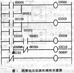
3. The system test system applies the dual channel concept, which allows on-line testing so that it still has continuous protection during testing. PLC internal logic design uses a test circuit. The external output device also has independent two-way channels, thus ensuring the operating procedures of the periodic protection channel test.
3.1 Test Blocks This system has designed three test blocks, namely EH oil pressure test block, lubricating oil pressure test block and vacuum test block. The principle of each test block is the same. The principle is shown in Figure 2:
In Fig. 2, J1 and J2 are throttles; F, F1 and F2 are manual valves; S1 and S2 are solenoid valves; B1 and B2 are pressure gauges; K1, K2, K3 and K4 are pressure switches.
The role of the orifice is to isolate the two paths. When tested, do not interfere with each other. The test can be manually conducted on site or remotely through the test button in the main control room. When using the button test, there is a latch on the circuit to ensure that no two-way simultaneous test is performed. If the test is performed at the same time, it will cause a false trip. When testing manually, pay special attention to:
Under normal conditions, the pressure oil is sent to the pressure switch and indicating meter through the orifice. Once the oil pressure is reduced, each of the four pressure switches on both sides will have a switching action, which will cause tripping. The logical relationship is shown in Figure 3: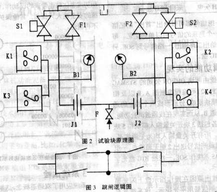
As shown in Figure 3, the "two or one" relationship can prevent erroneous jumps and prevent refusal jumps. During the test, when F1 or S1 is turned on, the indication on B1 will slowly decrease. When the set value is reached, K1 and K3 will operate. The indicator light is on the test plate. The test block solenoid valve power is 220VAC. After the test is finished, it is necessary to pay attention to whether the gauge pressure is restored to the normal value, otherwise it is not allowed to test another way.
There are six solenoid valves on the trip block, two OPC solenoid valves are normally closed 110VDC solenoid valves, and four AST solenoid valves are 110VAC normally open solenoid valves. Normally, AsT solenoid valves are normally charged structures.
3.2 In-line test set During normal operation, the online channel test can be completed through the ETS operation panel. At this point, the key switch on the operation panel should be in the "test" position.
Channel 1: Corresponds to AST1, AST3
Channel 2: Corresponds to AST2, AST4
When the system lubricating oil pressure, EH oil pressure and vacuum have been established, the head test module can be manually or remotely tested. The purpose is to check the ram speed of the punching medium and the reliability of the protection channel. In the single-channel test, regardless of whether the manual operation or the remote control test is performed on the spot, the speed of the head module to discharge the punching medium should not be less than the specified requirement. When doing the channel test, press the channel 1 or channel 2 button on the operation panel, ETS outputs a signal to the solenoid valve on the head test module, and the corresponding test channel signal is closed by the solenoid valve action, causing ASTl/AST3 or AST2/AST4 Actions to achieve channel online testing capabilities. In the test process, the operation status of the on-site tripping solenoid valve AST should be checked to confirm the correctness of the channel test state. In addition, when the channel test is done, the two channels should not affect each other, and the on-line test can only be a single-channel test and can be sent. The signal can in turn actuate the corresponding AST solenoid valve without tripping. After the test is completed, the key switch is set to the "Run" position.
3.3 Analog test panel test The analog test panel and the trip signal from the site are connected in parallel and sent to the programmable controller. Its function is to simulate the signal coming from the field and complete the static test of the ETS; check the input/output status of the programmable controller. Whether the status meets the requirements.
3.4 Operation panel test Let the analog test panel be in the off position. In the trip cabinet, the input signal from the scene in the system shall be short-circuited in order. The corresponding light on the operation panel shall flash, and the ETS trips the optical panel. Press the reset button on the operation panel to reset the trip signal. At the same time press the "trip" and "confirm" buttons on the operation panel, the unit trips and the ETS trips the light plate alarm. During the test, each time “hanging†or “trippingâ€, the operation of the on-site tripping solenoid valve (AST) should be checked to confirm the correctness of the “hanging brake†or “trip†status.
4. Improvement measures In the actual use process, we made the following changes:
(1) “The low turbine pressure ratio? The protection is repeated when the turbine rushes, which affects the turbine revolution, and it is normal that the turbine pressure ratio is low during the turbine revolution. Therefore, the signal goes to the trip chamber. Between the installation of a protective switching small switch, after the unit and the network into the protection.
(2) The original design of ETS only outputs the solenoid valve closing signal to the head test block. When the test button is turned on, the corresponding channel signal test can be realized without outputting to the AST solenoid valve signal, and the channel test is added to the AST after the debugging. The solenoid valve signal, that is, the online test, can send a signal to the head test block solenoid valve, and the corresponding AST solenoid valve can be operated without tripping.
(3) Attention should be paid to signal anti-jamming measures. During the trial operation of the unit, a single-alarm fault of the generator fault and a tripping accident caused by a tripartite generator fault occurred. After this signal was installed, intermediate relays were isolated and the problem was solved.
In addition, the back-up battery in the programmable controller is used to save the program and related settings. Insufficient power supply voltage will result in data loss. This system has designed the battery shortage voltage alarm, thermal workers should pay attention to inspection.
5, concluding remark This system uses the programmable controller to have the quite advanced nature, its advantage is obvious. Small size, compact structure, high reliability, easy installation and maintenance. More importantly, simple programming, easy program modification, and convenient and flexible system composition: Although PLC has been widely used in industrial control, our province is still used for 300MW units for the first time. From the system debugging and operation results, the system design function and practical aspects are mature. In the logical design, the "two or one" relationship is adopted, which can prevent erroneous jumps, prevent refusal jumps, and improve the reliability of the system.
PLC has been widely used in the field of industrial control, and is more commonly used in the power industry. For example, chemical water program control, condensate polishing system and ash removal system, Tongling Power Plant 300 MW unit, ETS system is the first in Anhui Province to use PLC Units that implement their logical functions.
1. System Introduction The emergency shutdown system (ETS) consists of a simulation test board, an operation indicator board, a head test module and a control cabinet. The function of ETS is to accept the signal of the field device, and send an alarm signal when the parameters of the steam turbine exceed the limit. And through the AST solenoid valve discharge EH high pressure oil, close all steam inlet valve, emergency stop.
When a certain parameter of the steam turbine reaches the trip value, the detection signal acting on the tripping cabinet is closed. After logic processing of the tripping cabinet, four AST solenoid valves are driven, and the high pressure oil of the automatic tripping tripping pipe is drained, so that the high and medium pressure main Valves and adjusting doors close quickly. If the turbine speeds up to 103%, the OPC protection signal is sent by the DEH, so that the high pressure oil system blocks the two OPC solenoid valves in the module, and the 0PC high pressure oil is drained to close the high and medium pressure control door. Since two reverse check gates are provided between the automatic shutdown tripping busbar and the OPC busbar, the high and medium pressure main valves are still in operation. When the overspeed reaches 110%, the emergency shutdown system (ETS) acts, quickly closing the high and medium pressure main valves and regulating the doors to achieve emergency shutdown.
The system provides dual channel protection, allowing online testing to continue to provide continuous protection during testing.
There are 15 ETS design shutdown projects in this project: EH low oil pressure, low lubricant pressure, low vacuum, large axial displacement, 110% overspeed, high vibration (#1-8 watts), generator failure, high exhaust temperature , Low turbine pressure ratio, large differential expansion, boiler MFT, high pressure, high pressure, manual shutdown and ATC turbine shutoff, DEH power loss, etc., as shown in Table 1.
Each set of signals can give a "first out" memory signal, ie the first incoming signal can be memorized separately. Each set of signals gives two outputs, one signal to the SOE and the other to the BTG disk.
2. Implementation of Logic Function The system consists of two OMRON SYSMACC200HE (CPU42) programmable controllers A and B and corresponding I/O modules, which form two independent channels A and B, respectively, to realize the online channel. Test function. The A and B channels each include 3 digital input modules and 5 output modules. All digital inputs are passive contacts. In addition, two sets of passive contacts are sent for each set of trip signals, one set is provided to the DAS system for SOE, and the other is set to the BTG disk optical plate alarm display.
The first cause of tripping is flashed on the operation indicator and the subsequent tripping signal is indicated by a flat light. The system has ETS power failure and PLC fault alarm and first-out trip signal memory function.
The system's operating power supply capacity is 220V2KVA, which is powered by redundant UPS power supply and security power supply. The AST solenoid valve (normally-energized, normally-open solenoid valve) has a power supply of 110VAC, which is to turn 220VAC into 110VAC through a transformer in the control cabinet.
Figure 1 is a ladder diagram of a lubricant trip trip. 00000, 00001, 00100, and 00101 are input contacts of the PIC; 03000, 03003, 03006, 03010, and 00600 are coils of the PLC and are used instead of hard relays. In the PLC, coils are used as output elements to control external devices or other contacts inside the PLC. During normal operation, the on-site lubricating oil pressure switch contact is disconnected. Once the oil pressure is low to the trip value, the pressure switch contact is closed. The coils 03000 and 03003 are energized. The normally open contact of the coil is closed, and the 03006 coil is energized. In this way, the final 00600 coil is de-energized, causing the AST solenoid valve to shut off, thereby shutting off the turbine intake valve and stopping it. It can be seen that the soft relay in the PLC is a device that cannot be seen or touched, and there is no need to worry about the malfunction caused by the accumulation of dust on the contacts or the adhesion of the aging, so that the safety of the protection system is greatly improved. Other protection logic is similar and will not be repeated.
3. The system test system applies the dual channel concept, which allows on-line testing so that it still has continuous protection during testing. PLC internal logic design uses a test circuit. The external output device also has independent two-way channels, thus ensuring the operating procedures of the periodic protection channel test.
3.1 Test Blocks This system has designed three test blocks, namely EH oil pressure test block, lubricating oil pressure test block and vacuum test block. The principle of each test block is the same. The principle is shown in Figure 2:
In Fig. 2, J1 and J2 are throttles; F, F1 and F2 are manual valves; S1 and S2 are solenoid valves; B1 and B2 are pressure gauges; K1, K2, K3 and K4 are pressure switches.
The role of the orifice is to isolate the two paths. When tested, do not interfere with each other. The test can be manually conducted on site or remotely through the test button in the main control room. When using the button test, there is a latch on the circuit to ensure that no two-way simultaneous test is performed. If the test is performed at the same time, it will cause a false trip. When testing manually, pay special attention to:
Under normal conditions, the pressure oil is sent to the pressure switch and indicating meter through the orifice. Once the oil pressure is reduced, each of the four pressure switches on both sides will have a switching action, which will cause tripping. The logical relationship is shown in Figure 3:
As shown in Figure 3, the "two or one" relationship can prevent erroneous jumps and prevent refusal jumps. During the test, when F1 or S1 is turned on, the indication on B1 will slowly decrease. When the set value is reached, K1 and K3 will operate. The indicator light is on the test plate. The test block solenoid valve power is 220VAC. After the test is finished, it is necessary to pay attention to whether the gauge pressure is restored to the normal value, otherwise it is not allowed to test another way.
There are six solenoid valves on the trip block, two OPC solenoid valves are normally closed 110VDC solenoid valves, and four AST solenoid valves are 110VAC normally open solenoid valves. Normally, AsT solenoid valves are normally charged structures.
3.2 In-line test set During normal operation, the online channel test can be completed through the ETS operation panel. At this point, the key switch on the operation panel should be in the "test" position.
Channel 1: Corresponds to AST1, AST3
Channel 2: Corresponds to AST2, AST4
When the system lubricating oil pressure, EH oil pressure and vacuum have been established, the head test module can be manually or remotely tested. The purpose is to check the ram speed of the punching medium and the reliability of the protection channel. In the single-channel test, regardless of whether the manual operation or the remote control test is performed on the spot, the speed of the head module to discharge the punching medium should not be less than the specified requirement. When doing the channel test, press the channel 1 or channel 2 button on the operation panel, ETS outputs a signal to the solenoid valve on the head test module, and the corresponding test channel signal is closed by the solenoid valve action, causing ASTl/AST3 or AST2/AST4 Actions to achieve channel online testing capabilities. In the test process, the operation status of the on-site tripping solenoid valve AST should be checked to confirm the correctness of the channel test state. In addition, when the channel test is done, the two channels should not affect each other, and the on-line test can only be a single-channel test and can be sent. The signal can in turn actuate the corresponding AST solenoid valve without tripping. After the test is completed, the key switch is set to the "Run" position.
3.3 Analog test panel test The analog test panel and the trip signal from the site are connected in parallel and sent to the programmable controller. Its function is to simulate the signal coming from the field and complete the static test of the ETS; check the input/output status of the programmable controller. Whether the status meets the requirements.
3.4 Operation panel test Let the analog test panel be in the off position. In the trip cabinet, the input signal from the scene in the system shall be short-circuited in order. The corresponding light on the operation panel shall flash, and the ETS trips the optical panel. Press the reset button on the operation panel to reset the trip signal. At the same time press the "trip" and "confirm" buttons on the operation panel, the unit trips and the ETS trips the light plate alarm. During the test, each time “hanging†or “trippingâ€, the operation of the on-site tripping solenoid valve (AST) should be checked to confirm the correctness of the “hanging brake†or “trip†status.
4. Improvement measures In the actual use process, we made the following changes:
(1) “The low turbine pressure ratio? The protection is repeated when the turbine rushes, which affects the turbine revolution, and it is normal that the turbine pressure ratio is low during the turbine revolution. Therefore, the signal goes to the trip chamber. Between the installation of a protective switching small switch, after the unit and the network into the protection.
(2) The original design of ETS only outputs the solenoid valve closing signal to the head test block. When the test button is turned on, the corresponding channel signal test can be realized without outputting to the AST solenoid valve signal, and the channel test is added to the AST after the debugging. The solenoid valve signal, that is, the online test, can send a signal to the head test block solenoid valve, and the corresponding AST solenoid valve can be operated without tripping.
(3) Attention should be paid to signal anti-jamming measures. During the trial operation of the unit, a single-alarm fault of the generator fault and a tripping accident caused by a tripartite generator fault occurred. After this signal was installed, intermediate relays were isolated and the problem was solved.
In addition, the back-up battery in the programmable controller is used to save the program and related settings. Insufficient power supply voltage will result in data loss. This system has designed the battery shortage voltage alarm, thermal workers should pay attention to inspection.
5, concluding remark This system uses the programmable controller to have the quite advanced nature, its advantage is obvious. Small size, compact structure, high reliability, easy installation and maintenance. More importantly, simple programming, easy program modification, and convenient and flexible system composition: Although PLC has been widely used in industrial control, our province is still used for 300MW units for the first time. From the system debugging and operation results, the system design function and practical aspects are mature. In the logical design, the "two or one" relationship is adopted, which can prevent erroneous jumps, prevent refusal jumps, and improve the reliability of the system.