Abstract: The electrical monitoring system (ECS) adopts the CSPA2O00 system of Beijing Sifang Huaneng Power Grid Control System Co., Ltd., ECS enters DCS through communication, and realizes integrated monitoring of DCS. This method is the first application in the national thermal power unit.
Foreword:
The DCS of the 2×3OOMW steam turbine generator set used in Phase VI expansion project of Xuanwei Power Generation Co., Ltd. adopts the MAXDNA system from MCS, Inc., including MCS, Sequential Control System SCS, Furnace Safety Monitoring System FSSS, Data Acquisition and Processing System DAS, and Steam Turbine Digital Electric. Fluid control system DEH, steam-driven water pump digital electrohydraulic control system MEH, turbine emergency shutdown system ETS and other subsystems.
First, DCS system network MAXDNA system uses dual Ethernet (NetworkA and NetworkB), using standard TCP/IP communication protocol, physical star type, logical ring topology, connecting all workstations and distributed processing unit (DPU). Communication network redundancy ensures maximum system availability and data fault tolerance. The network bandwidth can be as high as 1 Gb/s, which is sufficient for the communication load requirements of large control systems. Each station on the network has two redundant network interfaces. The workstation and the DPU are directly connected to the network. The data communication between the workstation and the DPU does not need to be transited by the server. The point-to-point communication between the DPU and the DPU is possible. Communication between workstations and workstations, between workstations and DPUs through broadcasting. Each workstation or DPU is a node on the network. They are at the same level, eliminating the two-tier structure in which DCS divided the network into control level and monitoring level and the communication bottleneck between them. The network uses a full-duplex intelligent switch (HUBSwitch). Its communication bandwidth exceeds 1OOMb/s. It supports Ethernet lOBASE-T type cables and Fast Ethernet 100BASE-TX type cables. It also supports lOBASE-FL and lOOBASE-FX. Optical cable. The full-duplex operation doubles the network communication efficiency and the effective bandwidth reaches 2OOMb. Intelligent switches support simultaneous multi-site communication, avoiding "collisions" and effectively overcoming the shortcomings of traditional Ethernet. The software uses backplane SBP, which runs on DCS workstations to provide and process real-time data communication between workstations in the same domain. SBP can be regarded as a virtual data broadband. By sharing the real-time data collected and processed by the DPU through SBP data, the distributed database becomes transparent.
II. Main functions of the electrical monitoring system ECS (1) The electrical equipment is controlled and managed on the DCS operator station. The DCS system can also authorize electrical operation on the ECS operator station.
(2) Plant power automation: rapid cutting of high-voltage power plant and low-voltage power plant and relay protection, monitoring, information management and equipment maintenance of the public part of the power plant.
(3) Unit electrical automation: including the monitoring and management of generator-transformer protection, generator recording, excitation, synchronization, UPS DC power system, and power meter.
(4) Monitoring and management of diesel generator sets.
(5) Network Control Automation (NCS) function: monitoring and remote operation of the booster station, and NCS is connected to the S.
(6) Anti-misoperation locking and operation of the electrical system.
(7) Motor control.
Third, the ECS system network ECS uses a hierarchical distributed structure, the system sub-station control layer, communication management layer and bay layer 3 layers. The station control layer consists of redundant 2 background servers, 2 operator station 1 engineering stations, 2 network switches (providing dual network operating environment), 2 gateways (connected with other systems) and 1 satellite timed device GPS composition. The station control layer is the control center of the entire ECS system. It completes the data collection, processing, display, monitoring, and management functions of the ECS system. After corresponding authorization, the corresponding equipment can be controlled. The communication management layer consists of a communication processor and communication network equipment. It is the key link of ECS. It completes the real-time information exchange between the station control layer and the bay layer, and can directly communicate with the DPU of the DCS system and complete various automations. The access of the device realizes the conversion and access functions of the physical media and communication protocol of communication, and supports the communication methods of field bus, Ethernet, and RS485. The spacer layer is composed of various kinds of measurement and control devices. It is the lowest layer of ECS and protects and monitors the corresponding electrical equipment. The spacer layer measurement and control device enters the ECS10OMb/s Ethernet through the communication processor via the Lonworks fieldbus.
IV. Communication between ECS and DCS Lonworks fieldbus is connected to the communication processor. On the one hand, the communication processor is connected to the serial communication card of DCS through the serial interface, and accesses ECS100Mb/s Ethernet through the Ethernet interface. The ECS network passes through the network. Bridge and DCSl00Mb/S Ethernet connection, in order to achieve DCS, ECS information exchange. Therefore, the intelligent, networked electrical measurement and control unit can be regarded as an electrical dedicated remote I/O module of the DPU in the DCS. The device control operation is completed by the DPU, through a serial communication card, a communication processor, a field bus, and a measurement and control unit. The start-stop control of electrical equipment realizes integrated monitoring and management of DCS and ECS.
V. Information integration between DCS and ECS The information integration of DCS and ECS requires that the time scales of the two system data must be unified, that is, the clocks of the two systems must be synchronized. According to the requirements of the computer monitoring system for thermal power plants, the clock synchronization accuracy of the system is (5~20) ms. Xuanwei Power Plant Phase VI expansion unit DCS and ECS have used the upper workstation as the time source, respectively broadcast the time to the DCS and ECS systems through the time-to-date software, but due to the uncertainty of ordinary Ethernet data transmission delay and WINDOWS operation Under the system, when the time-to-time program transmits the delay of the message, the accuracy of the time can only be within 150ms and cannot meet the requirement. For this reason, consider using two systems to time each other with a GPS satellite synchronized clock. The network structure and timing system of the unit control system are shown in Figure 1.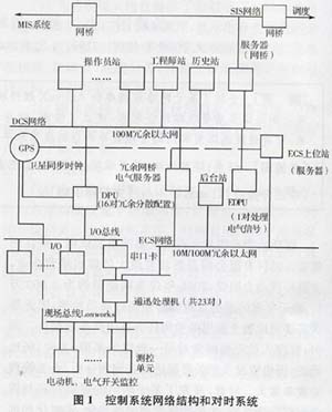
5. DCS system's time pair DCSl receives the time-lapse message from the GPS timing device through the coaxial cable to the DPU, and then through the dedicated Fast Ethernet to other DPU pairs of the unit's unit, and simultaneously passes through the DCS 1 upper station timing procedure. The time is opposite to the upper station of the DCS. After testing 80 times, it shows that the error between the DCS system and the GPS clock is within lmS.
5.2 ECS system's timing ECS ​​system timing signal is divided into 2 ways: All the way through the ECS system host station to the time program to receive the GPS serial device's serial port time message, through Ethernet timing to other host stations and all communication management machine broadcast At the time, the communication manager broadcasts the time to each of the measurement and control units in the segment to ensure that the system clock is the same in seconds. The other way is the hard-wired second pulse signal. The GPS time synchronization signal is connected to the second pulse-to-time channel of each measurement and control unit. The measurement and control unit performs an internal system clock millisecond GPS second pulse clearing process every 2 minutes interrupt. A total of 80 tests were performed. The recorded data showed that the error between ECS and GPS clock was within 5mS. In the 80 test records, there have been 2 SOE record loss phenomena. For this reason, Lonworks fieldbus communication data loss retransmission method is used to solve this problem.
When the DCS system and the ECS system are absolutely matched with the same reference device (ie GPS device) in the above manner, the DCS accuracy is 1 ms, and the ECS accuracy is 5 ms. Therefore, the time between the DCS system and the ECS system is correct. The accuracy is 5ms.
The integration of the electrical monitoring system into the DCS enabled the integrated control of the machine, electricity, and furnace to be simpler, safer, and more centralized and adaptable to the control needs of large-scale units. The field bus-based ECS system enters the DCS through the communication method, saves a large number of cables, and greatly reduces the engineering cost. It is an ideal method at present. When DCS and ECS perform GPS time synchronization, the accuracy is relatively high. Occurrence of occasional loss of SOE records in the ECS system has been resolved through the fieldbus retransmission mode. The main protection signals of the machine, furnace, and radio are all connected to the DCS. SOE records, so the system can meet the power plant operation requirements.