Foreword
With the development of modern sensor technology and wireless communication technology, the Internet of Things has begun to enter people's daily lives. The Internet of Things, represented by technologies such as RFID, ZigBee technology, and NFC near-field communication, is becoming the direction of R&D and innovation in many enterprises and universities. Although for these technologies, semiconductor manufacturers provide a variety of dedicated chips, and even highly integrated solutions, engineers still face many challenges when designing an actual IoT device. One of the most important factors is how to measure the time-dependent time and frequency domain signals in the system. The RF signal applied in RFID and ZigBee technology is not very complicated, but the quality, power and timing relationship of the signal determine whether the system can work normally. These RF parameters are not only related to the RF transmit/receive circuit, but also affected by the baseband circuit and the control circuit. The reading and writing of the internal registers, the operating conditions of the power supply, and even the delay time of the system all determine the operating status of the entire system. Traditional oscilloscopes or spectrum analyzers are unable to perform such time-correlated integrated debugging of the time and frequency domain signals.
The innovative design concept of the MDO Mixed Domain Oscilloscope The unique innovative concept of the Tektronix MDO4000 Series Mixed Domain Oscilloscope provides a unique tool for debugging cross-domain time-frequency related systems. Based on a full-featured mixed-signal oscilloscope, the MDO4000 adds a 3GHz or 6GHz spectrum analyzer that can perform a variety of frequency-domain measurement functions for common spectrum analyzers. The completely independent oscilloscope time domain acquisition system and spectrum analyzer frequency domain acquisition system can work independently or through triggering cooperation. By moving the spectrum time, the user can observe the spectrum of the RF signal collected at any point in the RF channel within the time window acquired by the oscilloscope. The MDO also provides modulation domain analysis of RF signal amplitude, frequency, and phase versus time. These unique features help users measure various modulation information of RF signals. One problem that engineers using spectrum analyzers often face is how to accurately trigger and capture the RF signal of interest. Due to the limited triggering capabilities of traditional spectrum analyzers, it is difficult for users to do so. The MDO4000 not only can trigger through various features of the RF signal, but also can use the oscilloscope's trigger system to complete the trigger collection of the RF signal through the baseband or control signal. This function greatly reduces the difficulty of modulating the Internet of Things device.
When debugging an RFID system, an important difficulty faced by engineers is how to measure the return signal of the tag. Because the amplitude of the return signal of the tag is very small, it is often difficult to capture this signal using an ordinary oscilloscope, let alone make further analysis of its amplitude and frequency. The main reason is that the dynamic range of an ordinary oscilloscope is only 40dB, and it is impossible to capture a weak tag signal. The MDO4000 has a 60dB dynamic range and noise floor as low as -152dB/Hz, which is well suited for the task of capturing reader signals and tag signals at the same time. Its unique time-domain waveform function of the AvST RF signal amplitude can even display the amplitude of the tag signal.
Here we take a 13.56MHz RFID reader system as an example to introduce the MDO4000 cross-domain debugging application.
Application of MDO Mixed Domain Oscilloscope in R & D System Development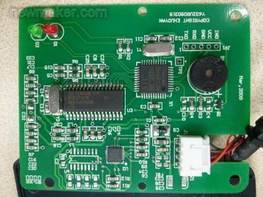
Testing RF signal quality parameters of 13.56 MHz RFID readers The 13.56 MHz high-frequency RFID system is currently the most widely used and mature radio frequency identification system in China. Relevant international standards have clear requirements for RF transmit frequency, channel bandwidth, transmit power, and other parameters. In particular, the RF signal amplitude (power) changes with time. The standard has strict regulations. Taking a read-write device as an example, the amplitude change time of the carrier signal emitted by the read/write device must meet the time limit of t1 to t4 of the ISO18000-3 standard.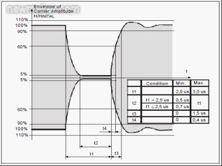
By using the unique triggering function of the MDO4000, users can easily and steadily capture RFID time and frequency domain signals. As shown in the figure, since the amplitude of the carrier signal is changing, it is difficult to measure the time length of T1 where the RF signal drops from 90% to 5% using conventional means. We can open the AvsT modulation curve, which represents the trajectory of the amplitude of the RF signal with respect to time. Through automatic measurement or manual cursor measurement, we can easily get the accurate time of T1. Similarly, other time parameters can be tested.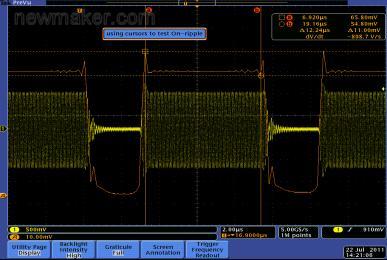

Test PCD to PICC read and write time Another time that needs to be strictly guaranteed is the time from when the reader sends a card read signal to the label return signal. If it is too long or too short, it will be read and written as failure. It is very difficult to use traditional instruments to measure these signals. The MDO4000 can display the AvsT trajectory of the RF signal on the screen. Users only need to use the cursor to locate the corresponding position. This delay time can be obtained.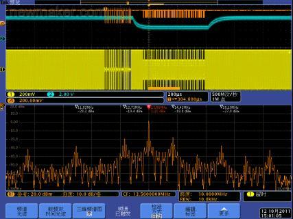
An RFID system using ASK modulation transmits data information through subcarriers. In the spectrum part above, we can clearly see that the carrier of the RF signal is 13.56 MHz and the subcarrier signal is about ±800 KHz. Meet the requirements of relevant regulations. If you need to measure radio frequency parameters of the RF signal, such as channel power, adjacent channel power ratio, or occupied bandwidth, you can directly display these measurement results on the screen by selecting the MDO4000's automatic measurement function.
If the designer wants to understand the data transmitted by the RFID system, the MDO4000 can also provide strong support. The MDO4000 can provide IQ data for RF signals. After these data are imported into Tektronix' RSAVu software, RFID data decoding and RF index calculations can be completed. As shown in the figure below, use RSAVu software to read the MDO4000 provides. With TIQ data, the software can calculate the time-domain waveform of the amplitude of the RF signal and calculate parameters such as EVM, modulation depth, modulation factor, frequency deviation, and code rate. And the data represented by these RF signals can be decoded and displayed. Simplify the difficulty of the designer's debugging.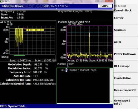
MDO's system-level debugging and analysis capabilities RFID readers are complex RF embedded systems that include baseband microcontrollers, RF transmit and receive modules, and power and control buses. Baseband control signals and the state of the system's internal registers directly affect the system's operating state. Take the reader-writer we tested as an example. The NXPCLRC632 read-write control chip contains voltage-controlled oscillators, phase-locked circuits, encoding, decoding, mixing and transmit/receive functions. The operation of the chip is controlled by the microcontroller chip STC90c58RD+.
Test system control signal timing relationship with TX and RX signals
The relevant pins of the NXPCLPC632 RF chip can measure the RF emission control signal. As shown in the above figure, the CH2 blue waveform can be measured simultaneously with the time domain waveform of the RF signal and the AvsT waveform of the RF signal. We can easily observe the impact of various control commands on RF emissions.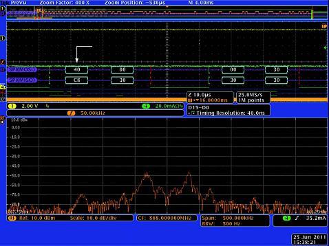
With the development of modern sensor technology and wireless communication technology, the Internet of Things has begun to enter people's daily lives. The Internet of Things, represented by technologies such as RFID, ZigBee technology, and NFC near-field communication, is becoming the direction of R&D and innovation in many enterprises and universities. Although for these technologies, semiconductor manufacturers provide a variety of dedicated chips, and even highly integrated solutions, engineers still face many challenges when designing an actual IoT device. One of the most important factors is how to measure the time-dependent time and frequency domain signals in the system. The RF signal applied in RFID and ZigBee technology is not very complicated, but the quality, power and timing relationship of the signal determine whether the system can work normally. These RF parameters are not only related to the RF transmit/receive circuit, but also affected by the baseband circuit and the control circuit. The reading and writing of the internal registers, the operating conditions of the power supply, and even the delay time of the system all determine the operating status of the entire system. Traditional oscilloscopes or spectrum analyzers are unable to perform such time-correlated integrated debugging of the time and frequency domain signals.
The innovative design concept of the MDO Mixed Domain Oscilloscope The unique innovative concept of the Tektronix MDO4000 Series Mixed Domain Oscilloscope provides a unique tool for debugging cross-domain time-frequency related systems. Based on a full-featured mixed-signal oscilloscope, the MDO4000 adds a 3GHz or 6GHz spectrum analyzer that can perform a variety of frequency-domain measurement functions for common spectrum analyzers. The completely independent oscilloscope time domain acquisition system and spectrum analyzer frequency domain acquisition system can work independently or through triggering cooperation. By moving the spectrum time, the user can observe the spectrum of the RF signal collected at any point in the RF channel within the time window acquired by the oscilloscope. The MDO also provides modulation domain analysis of RF signal amplitude, frequency, and phase versus time. These unique features help users measure various modulation information of RF signals. One problem that engineers using spectrum analyzers often face is how to accurately trigger and capture the RF signal of interest. Due to the limited triggering capabilities of traditional spectrum analyzers, it is difficult for users to do so. The MDO4000 not only can trigger through various features of the RF signal, but also can use the oscilloscope's trigger system to complete the trigger collection of the RF signal through the baseband or control signal. This function greatly reduces the difficulty of modulating the Internet of Things device.
When debugging an RFID system, an important difficulty faced by engineers is how to measure the return signal of the tag. Because the amplitude of the return signal of the tag is very small, it is often difficult to capture this signal using an ordinary oscilloscope, let alone make further analysis of its amplitude and frequency. The main reason is that the dynamic range of an ordinary oscilloscope is only 40dB, and it is impossible to capture a weak tag signal. The MDO4000 has a 60dB dynamic range and noise floor as low as -152dB/Hz, which is well suited for the task of capturing reader signals and tag signals at the same time. Its unique time-domain waveform function of the AvST RF signal amplitude can even display the amplitude of the tag signal.
Here we take a 13.56MHz RFID reader system as an example to introduce the MDO4000 cross-domain debugging application.
Application of MDO Mixed Domain Oscilloscope in R & D System Development
Figure 1: RFID readers using the NXPCLRC632 chip
Testing RF signal quality parameters of 13.56 MHz RFID readers The 13.56 MHz high-frequency RFID system is currently the most widely used and mature radio frequency identification system in China. Relevant international standards have clear requirements for RF transmit frequency, channel bandwidth, transmit power, and other parameters. In particular, the RF signal amplitude (power) changes with time. The standard has strict regulations. Taking a read-write device as an example, the amplitude change time of the carrier signal emitted by the read/write device must meet the time limit of t1 to t4 of the ISO18000-3 standard.
Figure 2 ISO18000-313.56MHz RFID air interface time parameter specification
By using the unique triggering function of the MDO4000, users can easily and steadily capture RFID time and frequency domain signals. As shown in the figure, since the amplitude of the carrier signal is changing, it is difficult to measure the time length of T1 where the RF signal drops from 90% to 5% using conventional means. We can open the AvsT modulation curve, which represents the trajectory of the amplitude of the RF signal with respect to time. Through automatic measurement or manual cursor measurement, we can easily get the accurate time of T1. Similarly, other time parameters can be tested.
Figure III. Time Domain and AvsT Modulation Domain Waveforms for a 56MHz RFIDPCD-to-PICC Signal
Figure 4: Measure the delay between the PCD transmit signal and the tag return signal
Test PCD to PICC read and write time Another time that needs to be strictly guaranteed is the time from when the reader sends a card read signal to the label return signal. If it is too long or too short, it will be read and written as failure. It is very difficult to use traditional instruments to measure these signals. The MDO4000 can display the AvsT trajectory of the RF signal on the screen. Users only need to use the cursor to locate the corresponding position. This delay time can be obtained.
Figure 5: Time Domain Waveform, Modulation Domain Waveform, and Spectrum Display of 13.56MHz RFID RF Signal
An RFID system using ASK modulation transmits data information through subcarriers. In the spectrum part above, we can clearly see that the carrier of the RF signal is 13.56 MHz and the subcarrier signal is about ±800 KHz. Meet the requirements of relevant regulations. If you need to measure radio frequency parameters of the RF signal, such as channel power, adjacent channel power ratio, or occupied bandwidth, you can directly display these measurement results on the screen by selecting the MDO4000's automatic measurement function.
If the designer wants to understand the data transmitted by the RFID system, the MDO4000 can also provide strong support. The MDO4000 can provide IQ data for RF signals. After these data are imported into Tektronix' RSAVu software, RFID data decoding and RF index calculations can be completed. As shown in the figure below, use RSAVu software to read the MDO4000 provides. With TIQ data, the software can calculate the time-domain waveform of the amplitude of the RF signal and calculate parameters such as EVM, modulation depth, modulation factor, frequency deviation, and code rate. And the data represented by these RF signals can be decoded and displayed. Simplify the difficulty of the designer's debugging.
Figure 6: RSAVu Automatic Test and Decode Functions
MDO's system-level debugging and analysis capabilities RFID readers are complex RF embedded systems that include baseband microcontrollers, RF transmit and receive modules, and power and control buses. Baseband control signals and the state of the system's internal registers directly affect the system's operating state. Take the reader-writer we tested as an example. The NXPCLRC632 read-write control chip contains voltage-controlled oscillators, phase-locked circuits, encoding, decoding, mixing and transmit/receive functions. The operation of the chip is controlled by the microcontroller chip STC90c58RD+.
Test system control signal timing relationship with TX and RX signals
Figure 7: Time domain relationship between Rx signal and RF signal
The relevant pins of the NXPCLPC632 RF chip can measure the RF emission control signal. As shown in the above figure, the CH2 blue waveform can be measured simultaneously with the time domain waveform of the RF signal and the AvsT waveform of the RF signal. We can easily observe the impact of various control commands on RF emissions.
Figure 8: Capture Register Status Data via SPI Bus
MCU chip and read-write control chip communicate through SPI bus. The actual work function of the read/write control chip is managed by changing the value of the internal register. For example, the address 14 register is the codercONtrol register, which controls the encoding clock and mode. When the third to fifth bits of this register are 000, the encoding rate is 848 KB. When the value is 011, it is a typical ISO 1443A encoding standard, the code rate is 106 KB, and the value is 100 when it is ISO 1443 TYPE B. The coding rate. In this debugging and actual combat, if we find that the frequency of the spectrum subcarrier signal is inconsistent with the transmission code rate that we designed, we can capture the SPI bus data of the corresponding address and check the value of the corresponding register to determine the cause of such a problem. The 0-2 bits of the Codercontrol register control the encoding of the transmitted data. If there is a problem that data communication cannot be established in the design debugging, you can check the three digits and check whether the actual coding form is correct. "000" represents the NRZ non-return-to-zero encoding of ISO14443-B, "001" represents the Miller encoding of ISO14443A, and "110" and "111" represent the encoding format corresponding to the ISO15693 standard.
to sum up
The unique time-dependent cross-over analysis function of the MDO4000 mixed signal oscilloscope provides a powerful tool for the development and debugging of IoT devices represented by RFID. Using the MDO4000 not only makes it easy to measure the signal's analog waveforms, spectrum conditions, and various frequency-domain parameters, but it also makes it easy to verify that the product complies with international and industry-standard regulations by using modulation trajectories such as AvsT, FvsT, and ΦvsT. More importantly, since the analog signal, digital signal, and bus signal are correlated with the RF signal in time, we can verify the actual working process of the system through these signal timing relationships, and can also pass the bus signal and register data. Analysis to find the cause of the failure. The MDO4000 is currently the only test instrument in the market that offers such functionality. We hope that MDO4000 will accelerate the design of IoT products and contribute to the development of the entire industry.