Abstract : This paper introduces the DCS reconstruction project of 200MW thermal power generating unit of Guangxi Liuzhou Power Generation Co., Ltd. and its problems and solutions in the process of transformation. The thermal control system after the transformation is operating normally, all technical indicators meet the requirements, and the transformation has been achieved. The intended purpose.
1. Unit Profile The installed capacity of Guangxi Liuzhou Power Generation Co., Ltd. is domestically produced two 200MW thermal power generating units, of which the 2# unit was put into operation in 1995. The main equipment is as follows:
Boiler: a Wuhan boiler factory; a model WGZ670/13.7-3; rated evaporation of a 670T / H; superheated steam pressure of a 13.72MPa; superheated steam temperature of 540 ° C; reheat steam temperature of a 540 ° C; The reheat steam pressure was 2.52 MPa; the reheat steam flow was 581.9 T/H.
Steam Turbine: A manufacturer of a heavy-duty motor factory in Beijing; model number N200-12.7/535/535.
Turbine Generators: A manufacturer of heavy-duty motor plants in Beijing; Model No. 1 QFQS-200-2; Rated power of a 235000/200000KVA/KW; Rated speed of 3000r/min; Cooling method of a water - hydrogen - hydrogen.
2. Existing problems in transformation 2.1 The original thermal control system adopts the YS-80 series digital adjustment meters and JKDT digital assembly meters produced by Xi'an Instrument Factory. The computer data acquisition and monitoring system (DAS) uses the EDPF-1000NEW type produced by the Institute of Electrical Engineering. among them:
· The YS-80 and JKDT systems are complex in structure. When they are designed, the functions of the two are overlapped with each other. Moreover, the equipment has a high failure rate, low reliability and safety, a large maintenance workload, and poor control performance and accuracy.
• DAS is a phase-out product of the EDPF-1000NEW of the Institute of Electrical and Electronics Technology. Due to the single and backward function, it is no longer sufficient to meet the requirements of unit operation and management.
· The two units adopt a large number of conventional instruments, which not only has a high failure rate, but also cannot accurately reflect the operation status of the units, but also increases the amount of maintenance work and the cost of spare parts.
• The protection equipment is numerous and complex. It is necessary to carry out a large number of protection experiments manually for each startup and shutdown group, and it is difficult to increase the efficiency.
2.2 Design Ideas The DCS to be adopted by the company must be "high reliability, advanced technology, and powerful functions" and try to reduce backup hard hands. According to the above principles, the DCS transformation of Design Unit 2 should meet the following requirements:
1 with DAS (Data Acquisition System), CCS (Analog Control System), SCS (Sequential Control System), ECS (Electrical Control System), FSSS (Furnace Monitoring and Protection System), DEH (Turbo Motor Control System) 6 Big function
2 unit control room changed to two machines and one control;
The 3DEH function is integrated into the DCS, the DEH operator station and the hard keyboard are canceled, and the operation is unified by the operator station;
4Include DCS in the electrical system, cancel all electrical operation panel, and complete the automatic grid connection, sequence control and other operations of the factory electrical switch;
5 Start and stop sequence control of all kinds of auxiliary machines into DCS;
6 When the public system is included in the DCS, both units can operate the public system after the DCS is completed;
7 to achieve FSSS function, including the ignition program control, fire protection, combustion optimization function;
8 Protection and interlocking into DCS.
3. Transformation Plan The DCS transformation of Unit 2# is entirely based on the MACS system of Beijing Helisi System Engineering Co., Ltd.
The system is configured with two domains: a common system for the 0# domain, a #2 unit for the #1 domain, and a #1 unit for the #2 domain, which is completed when the #1 unit is overhauled. A total of 12 field control stations are configured; 4 operator stations; 1 large-screen projector; and 1 engineer station; each domain is equipped with a pair of redundant servers. The operator station can switch to the public system through the inter-domain to realize the monitoring and operation of the common system equipment.
The operation bench is equipped with backup manual operation buttons divided into: emergency shutdown, emergency shutdown, start DC lubricant pump, main oil switch trip.
The equipments of the vertical plate layout are: steam drum electric contact water level gauge (2 pieces), synchronous table, quasi-synchronous controller, furnace flame monitoring industrial television, and steam drum water level monitoring industrial television.
Reserve the original scheduled and soot blowing control cabinets, DCS can start and stop them to control and monitor. Steam Turbine Monitoring System (TSl3300) Reserved.
DCS is divided into CCS, SCS, DAS, FSSS, and DEH functions, among which ECS is divided into SCS and DAS; FSSS includes ignition program control, fire protection, and combustion optimization guidance is divided into DAS.
The system has a total of 4403 I/O measuring points and a spare margin of 15%.
4. Characteristics of the control system 4.1 CCS
CCS realizes automatic control of the boiler and machine parameters such as water level, temperature, pressure and load. The analog control output adopts redundant configuration, which greatly improves the reliability of the automatic control system. The switch control output uses a special servo motor control module, which has the advantages of fast control speed and high sensitivity. The coordinated control system is provided with a boiler-following-based coordination method and a turbine-following-based coordination method. The two methods can be bumplessly switched by cutting buttons.
In the coordinated control system based on the boiler following, the main controller on the engine side uses the system power as the main signal and introduces the main steam pressure deviation signal. When the main steam pressure has a large deviation, it can ensure that the changes on the furnace side can keep up with the stable. The main controller of the furnace side uses the main steam pressure as the main signal and introduces the feedforward signal of the load deviation to ensure that the furnace side can quickly respond to the changes on the machine side.
In the coordinating control system based on turbine follow-up, the main engine side controller uses the main steam pressure as the main signal to introduce the power deviation signal to avoid excessive deviation of the main controller of the furnace side caused by excessive power deviation, causing the boiler to fail to burn. stable. The furnace side main controller takes the power signal as the main signal and introduces the power signal as a feedforward signal.
There are two operating modes, constant pressure and sliding pressure, which can be switched according to the operating conditions.
The holding function is provided in the load setting. If it is necessary to temporarily stop the lifting of the load during the lifting load process, the purpose can be achieved by maintaining the function. ADS mode and ALR mode are optional.
The RUNBACK function includes: sending, draught fan single trip, MFT action, generator demagnetization.
DEH has closed-loop control such as power control, pressure control and valve position control. When the DEH is put into power control and the main steam pressure is automatically controlled on the furnace side, the main steam pressure and load can be kept stable.
4.2 SCS
SCS realizes remote control, interlock protection and sequence control of electric doors, actuators, pumps and fans.
(1) Low-energy steam-powered electric gates can be used for single operation as well as group control.
(2) Interlocking between pumps realizes soft logic and low value interlocking of pumps, such as low voltage and low oil pressure, to achieve soft interlock.
(3) The boiler large interlock implements the soft logic, and the original external hard wiring is completely cancelled.
(4) soot blowing, scheduled scheduling control to keep the original control cabinet. DCS only realizes soot blowing, start and stop of scheduled program control, and monitoring of programmed interrupts.
(5) Most of the equipment groups are designed with sequential control, which is of great significance for the automation of the sequential startup and shutdown of major equipment. The sequence control of the equipment group includes the following: milling system subgroup, air supply system subgroup, inducer subgroup, feedwater pump subgroup, vacuum pump subgroup, low additive group electric door subgroup, and high-addition group electric door subgroup. Shaft seal fan subgroup.
4.3 FSSS
The FSSS realizes the automatic ignition of the boiler and the safety protection of the furnace.
(1) Boiler ignition program control to complete diagonal oil gun, single oil gun input program control;
(2) Furnace safety protection to achieve fuel interruption, drum level, furnace negative pressure, furnace fire and other protection items.
4.4 ECS
ECS realizes the start, adjustment, and stop of electrical equipment, monitors the working conditions of electrical equipment, and periodically checks major equipment. It mainly realizes the automatic grid-connected and automatic de-listing of generators, the sequence control of factory electricity switching, the interlocking between pumps and power supplies, and the operation and monitoring of all electrical equipment. 4.5DAS
·Responsible for the monitoring of data acquisition parameters; processing, complete monitoring of unit equipment status and parameters;
· Report management, print management;
·Accident recall can be used to recall the relevant switch quantity and analog quantity of the accident source;
· Storage and retrieval of historical data;
• Record full diary, simplified journal, operating diary, equipment diary;
· The performance of small indicators calculates and calculates the main steam pressure, main steam flow, main steam temperature and other indicators for each class, and forms a report.
4.6 Combustion Optimization Management System The combustion optimization management system calculates the -, secondary and tertiary wind speeds and pulverized coal concentration and instructs the operating personnel to carry out combustion adjustments. Calculate boiler efficiency, turbine efficiency.
(1) Calculation of pulverized coal concentration: The measurement and calculation of pulverized coal concentration shall be based on the measurement of the temperature change before and after the mixing of the primary air and the pulverized coal, and shall be calculated based on the amount of heat released from the primary air equal to the heat absorbed by the pulverized coal.
(2) Wind speed calculation: Calculated according to Bernoulli's equation.
(3) Calculation of boiler efficiency Using anti-equilibrium efficiency calculation method (4) Calculation of turbine efficiency includes: turbine cylinder efficiency, turbine thermal efficiency, turbine heat rate, steam turbine steam rate, high steam flow rate, reheat steam flow, Power generation efficiency, differential and subcooling.
5. Problems encountered during commissioning and operation and processing (1) When the three-stage water-injecting electromagnetic valve and the low-cylinder water-jet electromagnetic valve are opened or closed, there is no position feedback, and it is difficult for the operating personnel to judge the switching condition of the valve. We installed a pressure switch behind the valve. When the solenoid valve is opened, the pipeline has water pressure. The pressure switch contact is turned on. The color of the valve on the screen turns red, otherwise it is green. The operator can judge the position of the valve through the change of color.
(2) In the original design scheme, there are no separate retreat switches for the high and low levels of the drum water level. If the water balance container is to be overhauled, it must exit the MFT. This is not allowed in actual operation. To this end, we have put the water level in the third level into the water level protection switch. Since the protection signal and the high and low three-value signals that produce the level of the steam drum water level are shared by the equalization container, it is reasonable to include the high and low second and third values ​​in the steam drum water level protection signal.
(3) The adjustment of the water level of the deaerator was originally performed through the condenser recirculation gate. The condensed water after low pressure heating is returned to the condenser through the recirculation door, which inevitably causes heat loss. For this reason, we adjusted the water level adjustment of the deaerator to be adjusted from the low-exhaust outlet to the deaerator control door. The condenser recirculation gate serves as an auxiliary regulation. When the load is low, it is mainly regulated by the condenser recirculation door. When the load is greater than 60% (120MW), the condenser recirculation door is completely closed, and the deaerator water level is adjusted from the low addition outlet to the deaerator adjustment door. At the same time, in order to avoid overpressure caused by over-regulation after the valve is closed, the damage is low. In particular, a logic was added: The load was greater than 60% (120 MW) and the condensate flow at the outlet of the outlet to the deaerator regulator was less than 240 tons/hour, and the condenser recirculation door was opened automatically. In this logic, it may be more reasonable to use the condensate outlet pressure or the low outlet pressure as an automatic switch of the condenser recirculation door. However, due to the large error in the outlet pressure of the condensate pump, there is no pressure transmitter installed at the outlet. It is also reasonable to select the load and condensate flow as the condenser recirculation gate movement amount.
(4) The electric door opening indication is originally realized by the magnitude of the feedback current. The voltage is applied to the variable resistor in the electric door to generate a variable current. This method is simple but has the disadvantages of high breakdown rate of the transformer rectifier and difficulty in indicating adjustment. Direct measurement of the resistance of the variable resistor in the electric door can greatly reduce the intermediate links, and the resistance is converted into a percentage by the internal configuration.
6. Operation (1) After the DCS transformation, the automation level of the unit is improved, the automatic investment rate reaches 100%, and the adjustment quality is greatly improved. The operation of the unit is more economical, safe and stable. The main parameters of the automatic control performance indicators in Table l.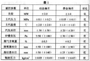
Disturbance method: step; perturbation; 30 MW (values ​​in parentheses are indicators before retrofit)
(2) The investment rate for protection is 100%, and the conditions for investment are available except for the sequence control group outside the pulverizing system. The small sequence control of the pulverizing system, such as starting and stopping of the coal mill oil pump, can achieve the sequence control.
(3) The input of the combustion optimization guidance system can guide the operator to optimize the combustion.
7. Remaining issues Programmatic start-up and shutdown of the pulverizing system cannot be put into use. One of the reasons is that the switch between the recirculation door, the hot air door, the total air door, the cold air door and the powder exhaust fan inlet door of the coal mill directly affects the inlet pressure and the outlet temperature of the coal mill. In the process of starting and stopping the milling process, it is impossible to coordinate the actions of the above five regulating doors to ensure that the inlet pressure and the outlet temperature of the mill are within the normal range. The second reason is that the speed of the coal feeder cannot be effectively controlled, that is, the amount of coal cannot be controlled.