Battery technology for electric vehicles (EVs) and hybrid electric vehicles (HEVs) has made significant progress, not only has the battery energy density been steadily increased, but the battery can also be reliably charged and discharged thousands of times. If design engineers can make effective use of these technological advances, electric vehicles and hybrid electric vehicles have the potential to compete with traditional vehicles in terms of cost, reliability and longevity.
The capacity specified by a battery refers to the amount of power that the battery can provide from 100% state of charge to zero state of charge. Charging to 100% charge or discharging to zero charge quickly shortens battery life, so the battery should be carefully managed to avoid full charge or full discharge. Compared with working between 30% and 70% of the state of charge (using 40% capacity), the battery can be charged between 10% charge state and 90% charge state (using 80% of the specified capacity) The total number of times is reduced to 1/3 or lower.
Balancing between effective battery capacity and battery life presents challenges for battery system design engineers. Consider the case of utilizing 40% capacity and utilizing 80% capacity as mentioned above. If the system limits the battery to only use 40% of its capacity in order to extend battery life by a factor of three, the battery size must be doubled to obtain as much available capacity as with 80% capacity. But this will double the weight and volume of the battery system, increasing costs and reducing efficiency.
Automakers typically require a battery life of more than 10 years and specify the required battery capacity. The challenge for battery system design engineers is to do everything they can to achieve maximum capacity with the smallest battery pack. To achieve this goal, the battery system must carefully control and monitor the battery with sophisticated electronic circuitry.
Electric vehicle battery system
An electric vehicle battery pack is composed of a plurality of batteries stacked in series. A typical battery pack has about 96 batteries. For a Li-Ion battery that is charged to 4.2V, such a battery pack can produce a total voltage of more than 400V. Although the automotive power system treats the battery pack as a single high-voltage battery, charging and discharging the entire battery pack each time, the battery control system must consider each battery condition independently. If one of the battery packs has a slightly lower capacity than the other batteries, the state of charge will gradually deviate from the other batteries after multiple charge/discharge cycles. If the state of charge of this battery is not periodically balanced with other cells, it will eventually enter a deep discharge state, causing damage and eventually forming a battery pack failure. To prevent this from happening, the voltage of each battery must be monitored to determine the state of charge. In addition, there must be a device that allows the batteries to be individually charged or discharged to balance the state of charge of these batteries.
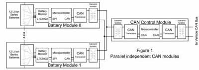
Figure 1: Parallel independent CAN module.
An important consideration in battery pack monitoring systems is the communication interface. For communication within the PC board, common options include the Serial Peripheral Interface (SPI) bus and the I2C bus, each with low communication overhead for low-interference environments. Another option is the Controller Area Network (CAN) bus, which is widely used in automotive applications. The CAN bus is very robust, with error detection and fault tolerance characteristics, but it has a large communication overhead and high material cost. Although the connection from the battery system to the car's main CAN bus is worthwhile, it is advantageous to use SPI or I2C communication within the battery pack.
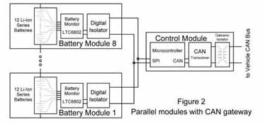
Figure 2: Parallel module with CAN gateway.
Linear has introduced a device that enables battery system design engineers to meet these demanding requirements. The LTC6802 is a battery pack monitor IC that measures the voltage of up to 12 stacked batteries. The LTC6802 also has an internal switch that allows the batteries to be discharged individually so that they can be balanced with other batteries in the battery pack.
To illustrate the battery pack architecture, consider a system with 96 lithium-ion batteries. This would require eight LTC6802s to monitor the entire battery pack, with each device operating at a different voltage. When using a 4.2V lithium-ion battery, the bottom monitor will be connected across 12 batteries, the potential adjustment range is 0~50.4V, and the voltage range of the next battery is 50.4V to 100.8V, following the battery pack. This type of push. Communication between these devices at different voltages presents an insurmountable challenge. Various methods have been considered, but each method has advantages and disadvantages due to the different priorities of the car manufacturers.
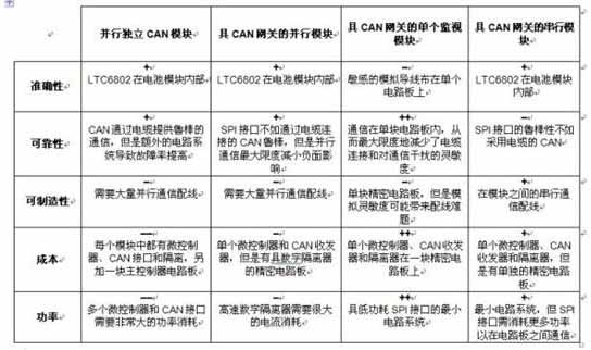
Table: Comparison of battery monitoring architectures.
Battery monitoring requirements
There are at least five major requirements that need to be balanced when making choices between battery monitoring system architectures. Their relative importance depends on the needs and expectations of the end customer.
1. Accuracy. In order to take advantage of the maximum possible battery capacity, the battery monitor needs to be accurate. However, the car is a noisy system with electromagnetic interference in a large frequency range. Any reduction in accuracy can have a detrimental effect on battery life and performance.
2. Reliability. Regardless of the power source used, car manufacturers must meet extremely high reliability standards. In addition, high energy capacity and the potential for instability of some battery technologies are major safety concerns. A fail-safe system that performs a shutdown operation under conservative conditions is preferable to severe battery failures, although it may unfortunately leave passengers stranded. Therefore, the battery system must be carefully monitored and controlled to ensure complete control of the entire battery life in the system. To minimize false and true failures, a well-designed battery system must have robust communication to minimize failure modes and fault detection.
3. Manufacturability. Modern cars already contain a large number of electronic products that use complex wiring harnesses. In the case of automotive manufacturing, adding complex electronic circuits and wiring to support an electric vehicle/hybrid electric vehicle battery system can make the complexity even higher. The total number of components and connections must be as small as possible to meet stringent size and weight constraints and to ensure that mass production is feasible.
4. Cost. Complex electronic control systems can be expensive, minimizing the relatively high cost of components such as microcontrollers, interface controllers, galvanic isolators, and crystals can significantly reduce the total cost of the system.
5. Power. The battery monitor itself is also the load of the battery, its lower operating current increases system efficiency, and the lower standby current prevents the battery from over-discharging after the car is turned off.
Battery monitoring architecture
Figure 1 through Figure 4 show the architecture of four battery monitoring systems. Suppose a system consisting of 96 batteries is divided into 8 groups by 12 batteries. The advantages and disadvantages of each architecture in this case are summarized in the table. In each case, an LTC6802 monitors a battery pack consisting of 12 batteries. Each architecture is designed as an autonomous battery monitoring system that provides a CAN bus interface to the car's main CAN bus and is galvanically isolated from the rest of the car.
1. Parallel independent CAN module (Figure 1)
Each module consisting of 12 batteries contains a circuit board with LTC6802, microcontroller, CAN interface and galvanic isolation transformer. The large amount of battery monitoring data required by the system will cause the car's main CAN bus to crash, so these CAN modules need to be on the local CAN subnet. The CAN subnet is coordinated by the main controller, which also provides a gateway to the car's main CAN bus.
2. Parallel module with CAN gateway (Figure 2)
Each module consisting of 12 batteries contains a circuit board with the LTC6802 and digital isolators on the board. These modules have an independent interface to the controller board, which contains a microcontroller, CAN interface, and galvanic isolation transformer. The microcontroller coordinates these modules and provides a gateway to the car's main CAN bus.
3. Single monitoring module with CAN gateway (Figure 3)
In this configuration, there is no monitoring and control circuitry inside the module consisting of 12 cells, but there are eight LTC6802 monitor ICs on a single board, each connected to its battery module. The LTC6802 device communicates over a non-isolated SPI-compatible serial interface. A single microcontroller controls all battery pack monitors via an SPI-compatible serial interface and acts as a gateway to the car's main CAN bus. Together with the CAN transceiver and galvanic isolation transformer, a complete battery monitoring system is formed.
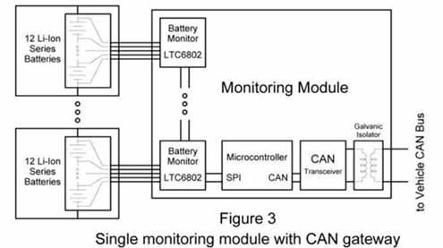
Figure 3: Single monitoring module with CAN gateway.
4. Serial module with CAN gateway (Figure 4)
This architecture is similar to a single monitoring module except that each LTC6802 is on a circuit board inside a module consisting of 12 batteries. These eight modules communicate via the LTC6802 non-isolated SPI-compatible serial interface, which requires three or four conductive cables to be connected between pairs of battery modules. A single microcontroller controls all battery pack monitors through the bottom monitor IC and doubles as a gateway to the car's main CAN bus. There is still a need for CAN transceivers and galvanic isolation transformers to form a complete battery monitoring system.
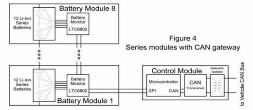
Figure 4: Serial module with CAN gateway.
Battery monitoring architecture selection
Since the parallel interface requires a large number of connections and external isolation, the first and second architectures are generally prone to problems. To address the increased complexity, design engineers need to implement independent communication to each monitor device. The third and fourth architectures are the least restrictive simplification methods. The LTC6802 meets the needs of all four configurations, and system designers can choose between two versions of the LTC6802, one for serial configuration and one for parallel configuration.
The LTC6802-1 is used in a stacked SPI interface configuration. Multiple LTC6802-1 devices can be serially connected via an interface that can send data back and forth along the battery pack without the need for an external level shifter or isolator. The LTC6802-2 allows a single device to be used in a parallel architecture. Both versions of the device have the same battery monitoring specifications and features.
Electric vehicles have a large demand for battery packs. Automakers want cost-effective battery systems to meet their stringent reliability requirements. Linear Technology's latest battery monitor IC gives system design engineers the flexibility to choose the best battery pack architecture without compromising performance.
Hydraulic Diaphragm Metering Pump/Hydraulic dosing pump, is characterized by the diaphragm reciprocating motion in the hydraulic work chamber, which means: the working chamber of the pump liquid end is caused from the diaphragm, but the diaphragm periodic motion is from the plunger reciprocating motion in the hydraulic work chamber, the accuracy of this dosing will be + 1%. The diaphragm is durable, and the component check valve ensure accurate ball control which in order to provide consistently accurate flow control through the pump, also it provide easy maintenance. The diaphragm technology provides high standard of safety, this eliminate the risk of leakage, then the pressure relief valve in the hydraulic end which to protect the overload problem. Under the different situation, hydraulic Diaphragm Metering Pump can be joined together in efficient configurations. The hydraulic diaphragm metering pump usually used in chemical and petrochemical, pharmaceutical, cosmetic, food production and packaging industry.
Hydraulic Diaphragm Metering Pump
Hydraulic Diaphragm Metering Pump,Manual Hydraulic Diaphragm Metering Pump,High Pressure Hydraulic Diaphragm Metering Pump,Electric Hydraulic Diaphragm Metering Pump,Hydraulic Dosing Pump
Zhejiang Ailipu Technology Co., LTD. , https://www.alipu.com