Yang Shuai1 Li Xingqin2 Li Ping1 Wang Changqing1
(1. Ankerui Electric Co., Ltd., Shanghai 201801)
(2. Southwest Sichuan Guangsha Architecture Design Institute Co., Ltd., Chengdu, Sichuan 610042, China)
Abstract: In an isolated power system, in order to prevent serious consequences due to multi-point grounding, it is necessary to perform real-time insulation monitoring of the system, and to locate the fault when monitoring the insulation fault. In this paper, based on the introduction of the working principle of the insulation location signal generator, the hardware and software design of the signal generator are described in detail. The products designed in this article have passed the test and can be applied to IT systems to provide safe and reliable power supply solutions for application sites.
Keywords: IT system signal generator fault location
0 Preface
In an IT system, a single-point ground fault is a very common failure. Once a single point of earth fault occurs, the IT system becomes a TN-S system. Although it can continue to run with faults, it has lost the advantages of IT systems and increased security risks. Therefore, it is required to monitor the insulation status of the system against the ground in real time, and when the insulation failure to ground is monitored, the fault point branch can be automatically located through the meter. If there is no automatic positioning function, once a failure occurs, it can only rely on the manual search of up to tens, hundreds, or even tens of thousands of load branches one by one. This will not only take time and effort, but also seriously undermine the continuity of the power supply. . This is not allowed in certain special places (such as hospital operating rooms) that require continuous power supply [1].
Based on the above situation, a signal generator for locating insulation faults is designed in this paper. It is installed in the IT system and can be used to implement insulation fault location function with the insulation fault locating device. When an IT system has an insulation fault, the signal generator activates and generates a positioning signal that is injected between the IT system and ground. The insulation fault location device patrols through the sensor, and when it detects that the positioning signal flows through a certain branch, it can determine that the branch is the circuit where the insulation fault is located. At this time, the operator can purposely perform power off or other protection operations against the faulty branch, eliminating the need to check the branch-by-branch power failure one by one, which not only improves the work efficiency but also effectively protects the continuity of the system power supply. Therefore, it is of great importance to the safety, continuity and reliability of power supply to the power system.
1 Principle of signal generation
The working principle of the signal generator is that when a single-point earth fault occurs in the IT system, the positioning signal is injected in turn between a certain line of the system and the earth so that the insulation fault locator can detect the positioning signal on the fault branch. The principle of occurrence shown in Figure 1 is often used.
Figure 1 The principle of signal generator

In an IT system, the effective value of the injected test signal must be small enough to avoid too much interference with the IT system or damage to the system load; and there must be a large enough peak to make enough current in the faulty branch. The fault locator current transformer can be monitored normally.
Considering the above two conditions, this paper uses pulse signals as test signals. If the amplitude of the pulse signal is sufficiently large and the width is sufficiently narrow, it can be achieved that the effective value is sufficiently small and the peak value is sufficient for the two desired targets. From a simplified design point of view, there is no need to directly generate a high-voltage pulse signal on the signal generator, which can be achieved by intercepting the peak of the AC signal in the IT system.
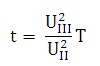
For a single AC IT system, the voltage between two lines L1 and L2 is AC220V, and the peak value is  To meet the requirement of a sufficiently large pulse peak. In order to meet the requirement that the effective value is sufficiently small, according to the IEC 61557-9 standard, "the effective value of the positioning signal voltage must not exceed 50V," the voltage threshold is set to 50V [2]. In this way, the pulse width can be calculated (since the pulse width is very small, this peak pulse can be regarded as ] The rectangular pulse).
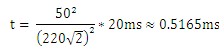
When the AC voltage cycle is 50Hz, pulse width
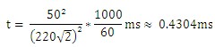
When the AC voltage is 60Hz, pulse width
Using the timer function of the SCM and optocoupler, the 0.4ms peak pulse can be accurately intercepted. Because 0.4ms <0.4304ms <0.5165ms, and the actual intercepted pulse signal, except for the peak, the remaining points are smaller than the amplitude Therefore, its effective value must be less than the set threshold 50V, and it can meet the requirement that the pulse effective value is sufficiently small.
2 Hardware Design
The designed hardware function module mainly includes a power supply module, a central control module, a monitoring module, a signal generation module, a communication module, and an indicator module. The hardware design principle block diagram is shown as in Fig. 2.
Figure 2 Hardware Design Block Diagram

After the signal generator is powered on, the CPU monitors the voltage of the IT system through the monitoring module in real time and measures the AC frequency of the IT system. When the system occurs insulation failure to the ground, the signal generator determines the pulse width and pulse frequency of the test signal according to the measured frequency, intercepts the system peak, generates a test signal, and alternately adds to the L1-PE and L2-PE. As a result of the insulation fault, the faulty branch can be equivalent to a relatively small value resistor, connecting the IT system fault line and ground to form a current loop, the test signal can generate a test current on the faulty branch, and the insulation fault locator can patrol one by one. When each branch is monitored, the test current is monitored on one branch and the branch can be determined as a failure branch. In this design, the central control module uses the 32-bit ARM CortexTM-M3 core microcontroller STM32F103 produced by ST. The chip has a fast processing speed and the maximum operating speed can reach 72MHz. The chip has a wealth of on-chip and peripheral resources, on-chip RAM 20KB and FLASH flash memory 64KB, with a multi-channel 12-bit A / D conversion module, and a number of SPI, I2C, CAN and other communication interfaces, which greatly simplifies the peripheral circuit design.
3 Software Design
The control program of the signal generator is written in C language. The structured program design method is used in the program design to facilitate the maintenance, migration and upgrade of the program code. After the system is powered on, it first completes the initialization and self-test of each module to ensure the reliability of the system work. After determining that the hardware circuits of each part of the system are normal, it automatically enters the normal operating mode. The main program flow chart of the system is shown in Figure 3. .
Figure 3 software flow chart

In order to fully ensure the accuracy and reliability of signal generator operation. The software uses a specific program algorithm for processing, which mainly includes:
(1) Digital filter algorithm. As the power system becomes more complex, the harmonic content in the power grid continues to increase. The first-hand signal collected by the signal generator naturally also contains a large number of harmonic components, as well as other noise interference. If these interferences are not filtered, they will have an impact on subsequent calculations. In order to avoid these effects, after the software acquires the data, it uses a digital filtering algorithm to filter out the part of the signal that contains harmonics, noise, etc., and only allows the useful signal to participate in the result calculation, so that the calculated result is more accurate. reliable.
(2) IT system AC frequency adaptive method. Because of the diversity of the working environment, the working voltage is not necessarily 50Hz, and the actual voltage frequency may be higher or lower. Therefore, the monitoring system needs to monitor the IT system's AC frequency in real time. The monitoring module will compare the voltages between the two L1 and L2 lines and time the UL1>UL2 and UL1 <UL2 respectively, denoted as t1 and t2. Since there is a certain threshold voltage when the voltage is compared, there is a phenomenon that t1>t2 or t2>t1. If t1+t2=20ms, that is, the system AC frequency is 50Hz, if a system-to-ground insulation fault occurs at this time, a section of width between (t1/2-0.2)ms and (t1/2+0.2)ms can be taken as For a pulse of 0.4 ms, a pulse of 0.4 ms in width is intercepted between (t2/2-0.2) ms and (t2/2+0.2) ms.
Figure 4 Voltage between L1 and L2 and Intercepted Pulse Voltage
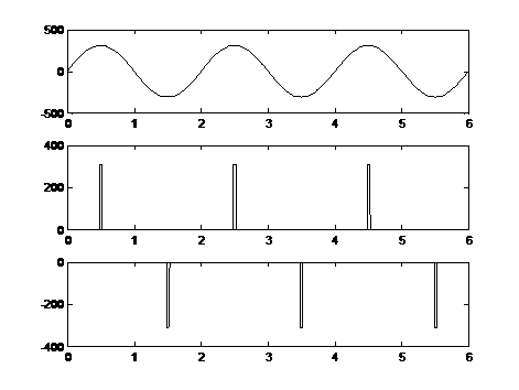
As shown in FIG. 4, during each period of the system voltage, the signal generator intercepts two pulses, respectively at the peak of the positive half-wave of L1-L2 (the second row in FIG. 4), and the negative half-wave of L1-L2. The crest (Figure 3, line 3). If the fault occurs on the L1 line, the pulse waveform intercepted at the peak of the negative half-wave of L1-L2 can appear positive on the faulty branch and can be monitored by the insulation fault locator; if the fault occurs on the L2 line Above, the pulse waveform intercepted at the peak of the positive half-wave of L1-L2 can appear positive on the faulty branch and can be monitored by the insulation fault locator.
If t1+t2=10ms, two pulses (L1-L2 positive half-waves, L1-L2 negative half-waves) can be intercepted instead of each pulse, taking into consideration the requirement that the effective pulse value is less than 50V. Secondary pulse (L1-L2 positive half wave, L1-L2 negative half wave). Other frequencies can be analogized in turn.
4 Signal Generator Application in Medical IT Insulation Monitoring and Fault Location System
Based on the signal generator designed in this paper, it has been successfully applied to an intensive care unit in a hospital. The system application is shown in Figure 5. Through the communication line, the insulation monitor, insulation fault locator and signal generator form a local area network. After the signal generator is powered on, it automatically enters the monitoring mode and monitors the frequency of the IT system. When the insulation monitor detects the insulation failure of the IT system to the ground, it starts the signal generator and insulation fault locator through the communication line and enters the signal generation mode and the fault location mode.
Figure 5 Application of an IT system in a hospital intensive care unit

In practical engineering applications, the pulse waveform generated by the signal generator is shown in Figure 6. It can be seen from the figure that there is a lot of clutter interference in this waveform, and the peak value is also higher than the theoretical one.  Small (Figure 6 sinusoidal waveform system voltage, as a comparison), but still meet the insulation fault location requirements, waveforms monitored in the insulation fault locator, after filtering and other pre-processing operations, as shown in Figure 7 .
Figure 6 waveform generated by the signal generator
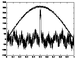
Figure 7 Waveforms Monitored by Insulation Fault Locator

It can be seen from Fig. 7 that the pulse waveforms monitored are much higher than the interference waveforms, forming a significant drop. By setting appropriate thresholds and matching pulse width conditions, it can be accurately determined whether this branch has been tested. The signal passes, that is, if there is an insulation fault in this branch.
After the fault branch is detected, the insulation fault locator displays the number of fault branches, and at the same time, the fault branch information is returned to the insulation monitor through the communication line. The insulation monitor immediately alarms, displays the number of faulty branches through the interface, and at the same time through the communication line, the command signal generator and the insulation fault locator stop the occurrence of signal and fault location, and the signal generator enters the monitoring mode again.
After the construction of the project is completed, the system is commissioned at the site to simulate 100 insulation failures and the insulation fault location rate is 100%. Fully prove that this design is feasible in engineering applications.
5 Conclusion
The signal generator of the insulation fault location designed in this paper has the function of adaptive IT system frequency, inject high peak value, low RMS pulse waveform, and can indicate the current working status through the panel indicator. Products based on this design meet the requirements of relevant national standards and can provide IT systems with safe and reliable power supply solutions. At the end of this paper, we also made a preliminary discussion on the location of IT system insulation faults in hospital intensive care units, and provided a reference for hospital electrical designers. In the application, the actual situation of different projects is very complicated and many new problems will be encountered. We hope that colleagues will further discuss.
Article Source: "Intelligent Building Electrical Technology," No. 1, 2014
references:
[1] JGJ 16-2008 Civil Building Electrical Design Specification [S].
[2]IEC 61557-9 Electrical safety in low voltage distribution systems up to 1 000 V ac and 1 500 V dc— Equipment for testing, measuring or monitoring of protective measures —
Part 9: Equipment for insulation fault location in IT systems
2 BURNER TEMPERED GLASS
2 BURNER TEMPERED GLASS
GUANGZHOU AIJINGSI TRADING LIMITED , https://www.aichugashob.com