Precise positioning or compensation of the position of the reference point of each axis. In CNC machine tools, in order to complete the machining of a part, it is often necessary to control the movement in several directions. This requires the establishment of a coordinate system for separate control, and the basis of the coordinate system is established. First, the zero point and reference point of the machine tool are determined. The machine zero is the design zero of the machine coordinate system. It belongs to the machine's inherent coordinate system and is established by the manual operation of the tool to return the tool to the reference point. The coordinate position of the machine zero and the machine reference point are fixed and stored in the CNC system. When the CNC system is started, the near reference point action is performed, thereby establishing various coordinate systems. The shaft displacement detecting component is replaced: the mounting position of the shaft displacement detecting component changes; the special grid position of the shaft displacement detecting component changes; the type of the axial displacement detecting component changes, and the structural characteristics of the axial displacement detecting component. The equipment has a certain space. Because the CNC machine tools used are special machine tools, the stroke design of each axis of the machine tool is relatively compact. Sometimes, when some tools and spare parts are not in place, there is still a certain space on the machine. In addition, due to some reasons that are difficult to judge for a while, the CNC system suddenly finds no reference point. Find out the resolution level of the axis displacement detecting element used in the CNC system. Generally, the center line of the spindle should be a fixed distance. Since this distance is not easy to detect, it is generally prepared by a simple machining program to move the tool to a certain size position first, then move it axially. round. The diameter of the outer circle is measured with a caliper and compared with the programmed size, the deviation value of the data in the memory is preset. When approaching the reference point operation, the positive direction over-range alarm occurs first when the reference point has not been found. In this case, the mechanical structure should be checked first. After confirming that there is no problem in the mechanical part and the axis movement space permits, move the positive direction hard overtravel block to the positive direction for a distance, and then try to return to the reference point operation; after finding the reference point, re-set the hard super The position of the block. Reason analysis of the reference point: related to the structure of the shaft displacement detecting element itself, the grating scale is taken as an example. Based on the characteristics of the grating scale structure, even if the reference point is customized, it is impossible to have a more refined selection. The selected activated reference point can generally only be the HOM E point closest to the machine tool requirement. At this time, the numerical control system 1850 CNC parameters can be used for compensation to achieve precise positioning. Due to the activated reference point position selection problem and the limitation of the reference point counter capacity, it is possible to find the reference point. (Finish)
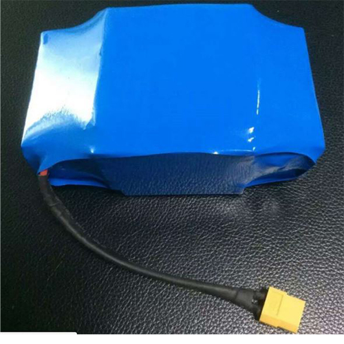
Electric Scooter Battery Pack is the heart of Electric Scooter;
A little bit different with traditional packing work, the scooter battery pack
has much more tech requirements for the IC parts and connection.
The basic quality standard of Electric Scooter Battery pack deeply rooted in the
18650 Lithium Battery cells and IC.

Electric Scooter Battery Pack
Electric Scooter Battery Pack,Electric Scooter Lithium Battery,Electric Bike Battery,Harley Electric Scooter Battery Pack
Shenzhen Mkarda Technology Co.,Ltd , http://www.mkarda.com